In Part I of this short series (Oct. 3, 2020), we pointed to certain stator defects coinciding with specific signatures that have been presented through observation. Regarding the induction motor itself, while substantial research on the defect signature associated with bearing faults, winding shorts, rotor faults, and air gap has been conducted by academic and commercial entities, alike, not much new information has emerged.
Furthermore, there’s been little research on stator-slot-related defects of coil movement, missing wedges and end-turn movement for either ESA or vibration. In fact, during the literature review for this three-part article series, only two technical papers were found from the vibration industry on stator-slot defects in electric machines.
The findings in the paper, “Analysis of State of Operation of Asynchronous Motor With Stator Slot Frequency Beat Vibration,” by Biernat and Goralski, Poland, 2017, discussed the discovery of a slot-pass frequency calculated as (N(1-s)f)/p where f is the supply frequency, N is stator slots, s is slip, and p are the number of pole pairs. This would indicate that a machine that had 54 stator slots and a running speed of 29.886 Hz, as with the wind generator example from Part I, would have a vibration slot pass frequency of 1804.68 Hz.
When applied to ESA, the vibration peak does not show up, but, instead, is identified as an amplitude modulated signal in which the sidebands of line frequency (carrier frequency) appear. In this case, the values would then be 1744.68 Hz and 1864.68 Hz, versus the 1553.8 Hz and 1673.8 Hz frequencies as described in the Part I article, as shown in Fig. 1.
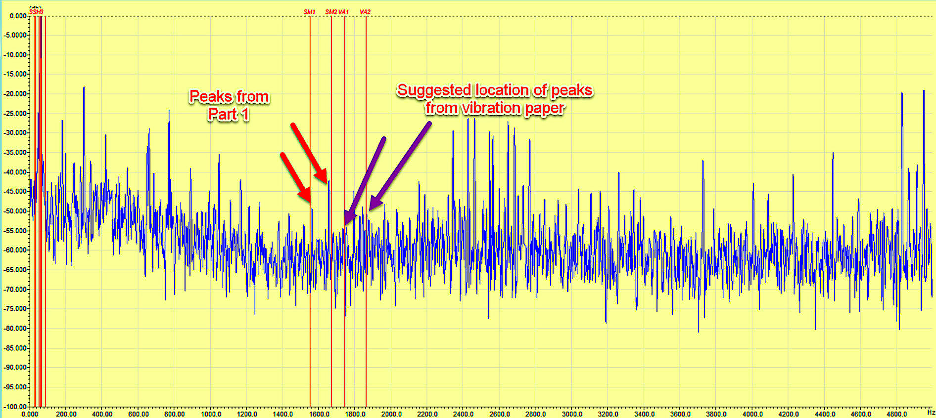
Fig. 1. Red arrows indicate peaks as calculated in Part I of this series, and Purple arrows
pointing to suggested location of peaks from the vibration paper reference in this Part II article.
As noted, in this machine, where there are known missing magnetic wedges, there are peaks where the standard calculation of running speed times stator slots plus and minus line frequency and no peaks that the vibration-related papers calculate as where the stator slot frequencies would be. A review of the paper further identifies that rotor bars are calculated in the same manner, which meets the data used in the example. A similar calculation is determined in the paper, “Vibration Diagnostics for Industrial Electric Motor Drives,” by Bruel & Kjaer, where we also find an explanation. The stator frequencies are assumed to be the same as rotor-slot frequencies, which present in the same manner. In both cases, the mathematical proofs of the stator and rotor-slot frequencies are viewed from a mechanical standpoint.
Personally, I would go a little further and mention that a few instances where stator- or rotor-vibration issues that are present in ESA analysis have been “missed” by vibration software intent on identifying the same issues. However, the peaks are present in the simpler rotor- or stator-slots-times-running-speed analysis, with different types of sidebands identifying different types of defects. What we have found is that not all FEA (Finite Element Analysis) analysis comes out correctly when trying to determine complex magnetic-field versus mechanical-analysis, and will normally solve for one or the other. Specialized FEM (Finite Element Method) analysis methods that view electrical, magnetic, and mechanical analysis (such as electric-machine-design software), tackle the differences as the method allows FEA to use more complex algorithms including the use of partial differential equations. At least, that’s our theory.
In the concluding article of this series (Part III), we will be focusing on several FEM-based models to confirm our theory, as well as determine if the simple rotor- or stator-slots-times-running-speed analysis to detect missing wedges or moving coils is correct.
Note that our theory is based simply upon observation: the stator force wave moves through the air gap at the synchronous speed, and the interaction between the rotor and stator fields lag by the slip of the speed. This means that the rotor bars or stator windings (or magnetic wedges) are subjected to a forcing motion radially as the magnetic fields peak and valley due to sinusoidal current. The solution is slightly more complex, as the peaks don’t appear at exactly the synchronous speed of the rotating fields, but lag closer to the running speed of the rotor in both instances.TRR
For Other Articles About Electrical Signature Analysis, Click On The Following Links:
August 22, 2020: “What Makes Electrical Signature Analysis Different?”
August 28, 2020: “ESA, MCSA, Rotor Bars, Shaft Fault and Bearing Wear“
Sept. 4, 2020: “Trending Rotor Bar Failures (Case Study)”
Sept. 11, 2020: “Electrical Signature Analysis and Pumps”
Sept. 17, 2020: “Electrical Signature Analysis (ESA) & Fan Belt Applications
ABOUT THE AUTHOR
Howard Penrose, Ph.D., CMRP, is Founder and President of Motor Doc LLC, Lombard, IL and, among other things, a Past Chair of the Society for Reliability and Maintenance Professionals, Atlanta (smrp.org). Email him at howard@motordoc.com, or info@motordoc.com, and/or visit motordoc.com.
Tags: motors, drives, generators, wind turbines, wind energy, motor testing, reliability, availability, maintenance, RAM, electrical signature analysis, ESA, motor current signature analysis, MCSA, vibration analysis

