
An area that has received limited research analysis within the topic of Electrical and Current Signature Analysis (ESA/MCSA) is the stator-slot signature. It’s been assumed for many decades that the number of stator slots times the running speed with different types of sidebands identify a variety of stator defects in vibration analysis. It’s also been expected that a similar multiplier would be present in ESA/MCSA testing.
General research in this area has been limited primarily to observation, with few readily-available academic research efforts and papers on the topic. Stator defects, though, have a greater impact than rotor bar defects, which is an area that has received a significant amount of commercial and academic research. In this three-part series on stator issues, we start with a review of some observations and follow that with an academic discussion of the theories behind them.
WIND-GENERATOR OBSERVATION
Our first observation involves a wind-generator unit that has 54 stator slots and operates at 1800 rpm, or 30 Hz. This example situation is reflective of a significant issue in the wind industry: stator wedges coming out of the slots. These wedges are magnetic, i.e., 80% to 95% ferrous material, which is meant to reduce temperature and noise during machine operation. Entering the air gap between the rotor and stator, the wedges are ground to dust over time. That dust subsequently enters the stator-insulation system, eventually causing the winding to fail to ground.
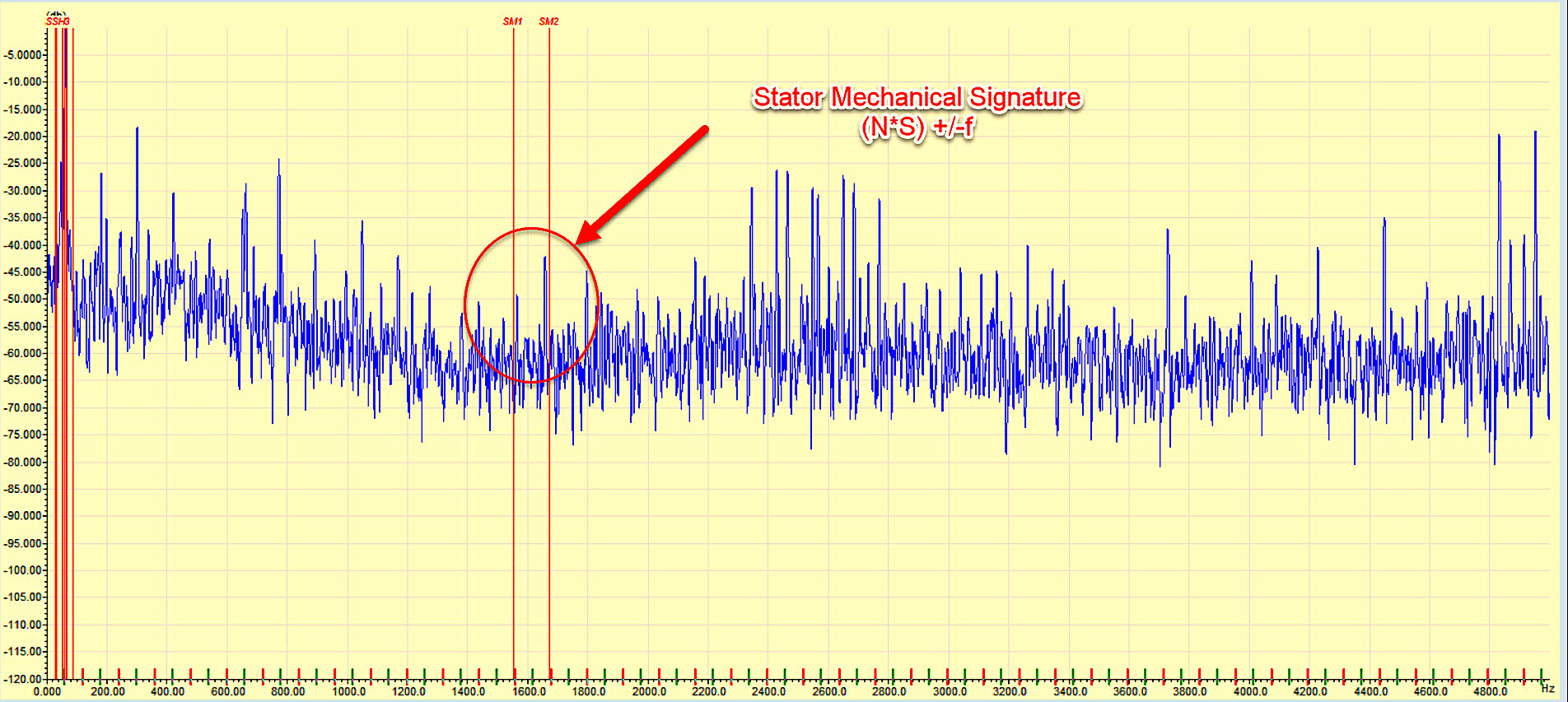
Fig. 1. Stator-slot signature where S is the number of slots, N is the running speed, and f is line frequency.
As seen in Fig. 1, the example generator’s measured running speed is 29.886 Hz (1793.2 rpm); there are 54 stator slots (N); and the 4-pole generator is 2 pole pairs (p). The signature would be (54ss*29.886)+/-60Hz which would be 1613.8Hz +/-60Hz (1553.8 Hz and 1673.8 Hz). The generator was evaluated and found as shown in Fig. 2.
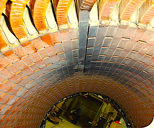
Fig. 2. Wind-generator stator with missing wedge and fault to ground.
The severity of the defect prior to the ground fault was detection of winding stress, as found in Fig. 3, where: fst is the frequency peaks of interest; f is the supply frequency; n is an integer from 1, 2, 3, etc.; k is an integer from 1, 2, 3, etc.; p are the pole pairs such as 3600 rpm is 2-poles or 1 pole pair; and, s is the slip, which is (Ns – N)/Ns where Ns is the synchronous speed and N is the running speed.
The winding stress may be partial discharge or slot sparking and insulation breakdown, where sparking occurs. It has been identified as a “winding short” frequency, but has also been found to be present in certain variable-frequency-drive (VFD) and missing-wedge conditions (Ref: “Evaluation of Stator and Rotor Interturn Stress with Electrical Signature Analysis in Variable Frequency Drive and Wind Generator Applications,” IEEE Electrical Insulation Conference, June, 2020, Penrose).
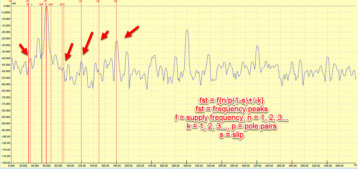
Fig. 3. Stator stress and sparking frequencies associated with winding insulation defects.
The combination of the two conditions outlined above identified that the generator was in distress prior to its failure to ground. The review of a combination of conditions allowed the analyst to identify the type and severity of defect.
ELECTRIC MOTOR OBSERVATION
Our second observation involves an 800-hp, 1785 rpm (29.75 Hz), 4160 Vac motor with 72 stator slots and an ESA- measured running speed of 29.877 Hz (1792.6 rpm). Figure 4 is the current obtained from this motor. The frequencies in question would be (29.877 Hz * 72 SS) +/- 60 Hz or 2091.14 Hz and 2211.14 Hz, indicating a stator-slot condition. Disassembly of the machine after failure showed as Fig. 5.
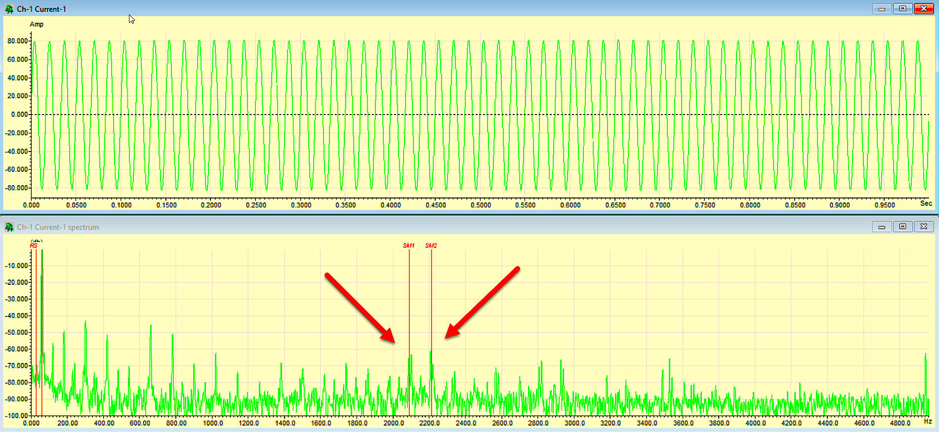
Fig. 4. Stator frequencies from an induction motor that repeatedly fails as the coils leave the stator slot.
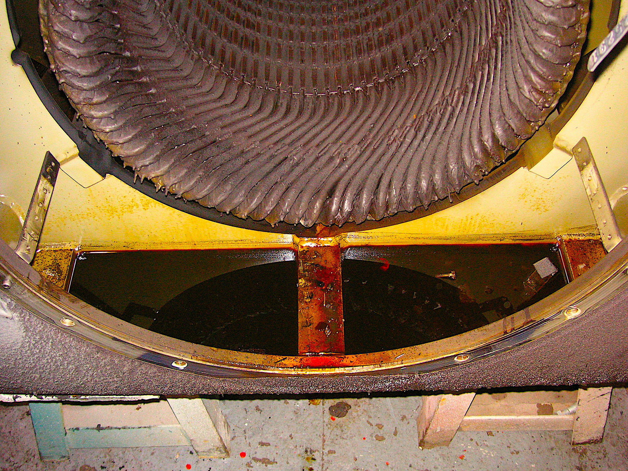
Fig. 5. Failed motor stator shorted to ground at the bottom, where the windings exit the stator core.
The stator coils were found to extend over one-third the length of the stator core on both ends. Stator winding anchors were present, but they weren’t attached (see Fig. 6). And there was only one surge ring on each side.
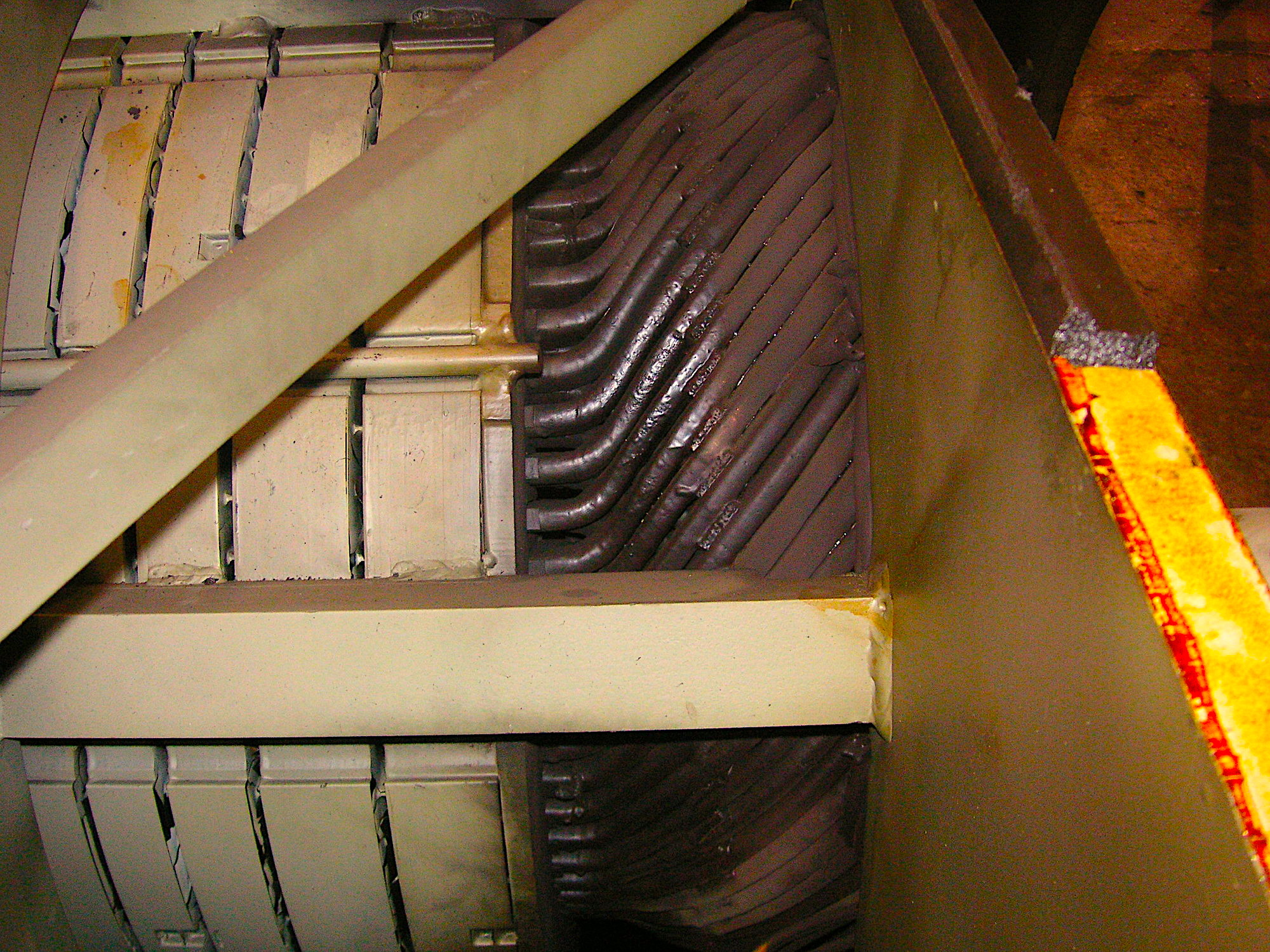
Fig. 6. Improperly braced winding extensions, resulting in winding failure.
In this case, the coil-end movement shows as the individual coil ends move in and away from the rotor as part of a moving magnetic force-wave that travels in the motor air gap. Interestingly, this case-study example actually involved six identical 800-hp electric motors. Those that had not yet failed showed the same signature after they had been repaired at one specific repair facility.
COMING UP
In my next article, we’ll review the existing academic papers that identify how the stator-slot multiplier theoretically works, which conflicts with the observations described here. We’ll follow that with a proposed theory as to why the slot frequencies show as they have been observed.TRR
To Read More From Howard Penrose About Electrical Signature Analysis, Click On The Following Article Links:
August 22, 2020: “What Makes Electrical Signature Analysis Different?”
August 28, 2020: “ESA, MCSA, Rotor Bars, Shaft Fault and Bearing Wear“
Sept. 4, 2020: “Trending Rotor Bar Failures (Case Study)”
Sept. 11, 2020: “Electrical Signature Analysis and Pumps”
Sept. 17, 2020: “Electrical Signature Analysis (ESA) & Fan Belt Applications
ABOUT THE AUTHOR
Howard Penrose, Ph.D., CMRP, is Founder and President of Motor Doc LLC, Lombard, IL and, among other things, a Past Chair of the Society for Reliability and Maintenance Professionals, Atlanta (smrp.org). Email him at howard@motordoc.com, or info@motordoc.com, and/or visit motordoc.com.
Tags: motors, drives, generators, wind turbines, wind energy, motor testing, reliability, availability, maintenance, RAM, electrical signature analysis, ESA, motor current signature analysis, MCSA

