
As discussed in my June 5, 2021, article (Part 8, see link below), taking a step back and looking at the bigger picture can change your perspective greatly. Consider, for example, unsatisfactory equipment operation, including not meeting expected performance; unexpected wear or defects; or consistent failures. Once such symptoms and/or defects have been identified, you might state a Root-Cause-Failure (RCA) hypothesis, but then be sure to follow up with actual analysis to uncover a more accurate cause. It’s important to reference “a more accurate cause,” rather than “the true cause,” as subsequent RCAs, results, or discoveries could change the findings or, even identify that what had been assumed to be the root cause, based on a previous RCA, was just another symptom.
In the following real-world case study, we only touch on a topic and research that’s now underway, as well as the original thinking related to various defects and failures identified as root causes. During a change in a routine testing methodology, additional information that became available altered the perspective of the involved stakeholders. Most of the prior research on this topic had concluded that certain conditions, under software simulations, would exist in certain environments. The challenge, if a study had identified a root-cause or led to additional work, is that the researchers were looking at narrow failure conditions, such as the transformer, generator, or gearbox, and not the entire system.
For purposes of this article, the term Sub-Synchronous Resonance (SSR) will be used to describe SSR, Sub-Synchronous Control Interaction (SSCI), and Sub-Synchronous Torsional Interaction (SSTI), which are the various conditions associated with the case study’s stated hypothesis.
A BIT OF BACKGROUND
To recap the discussion in Part 8: A nagging failure issue in the alternative-energy industry involves wind-turbine step-up transformers that increase voltage from 480V, 575V, 690V, or 750V to 33kV or 66kV. In fact, so many of these transformers outgas and fail that international standards have been written to address the problem, including, as an example, IEC/IEEE 60076-16, “Power Transformers – Part 16: Transformers for Wind Turbine Applications.” (This standard identifies unusual per-tower and transmission and distribution transformer issues associated with wind turbines.) Working groups within the industry are also addressing the problem. In the meantime, more working groups are addressing issues such as fracturing bearings and other conditions in the gearbox, while still others are addressing generator concerns. In effect, silos have developed among these groups, each with specific expertise in mechanical, electrical, or component conditions.
As mentioned in Part 8, my own literature search regarding the transformer issues found several events occurring in large utility generators between 2005 and 2010. Following those events, academic papers were published, and academic studies utilizing MatLab and Simulink software to simulate system events and make predictions were launched. A key takeaway from the research was that specific series of events can cause a recurrence of the transformer problems. What’s worse, the issue becomes greater as more systems are brought online.
With all this in mind, I embarked on my own investigation of specific wind-turbine-system issues. Involving a number of stakeholders, this real-world study leverages Electrical Signature Analysis (ESA), along with a variety of other technologies and information.
THE REAL-WORLD RESEARCH
In previous wind-turbine applications, we’ve normally collected data at the base of specific towers. For this investigation, however, data was collected up-tower, directly from the generator-connection box. The Intent was to put additional impedance between the controls and transformer and the conditions at the generator terminals (Fig. 1).
The ESA-data-collection system was set up to trigger on startup and collect 12,000 samples per second, at a resolution of 65,000 lines/inch. This allowed separation of power harmonics, sub-harmonics, and the various bearings, gears, and components throughout the system, including kW losses across each.
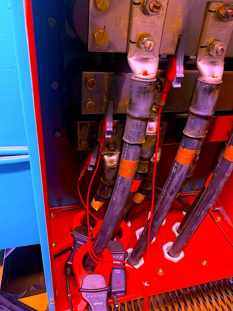
Fig. 1. Connections up-tower in a wind-turbine generator,
to help isolate data collection from the controls.
The tower was then restarted. The yaw motors position the nacelle toward the wind, and the pitch motors turn the blades so that they start turning with the wind. In the case of this tower, data was being collected at a wind speed of 5.8 m/s (13 mph), with gusts up to 8 m/s (18 mph) at 52 C ambient and overcast. This arrangement would provide certain effects, as the generator was lower down on the power curve, which plateaus at 7.9 m/s (rated output), and the controls produce reactive power to the rotor of this type of generator design (Fig. 2).
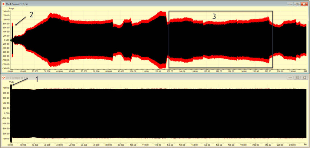
Fig. 2. (1) p-p voltage at closing of the main circuit breaker to the tower; (2) p-p current at closing of
the circuit breaker to the tower; (3) is “steady state” during variations in current output from wind gusts.
When zoomed in (Fig. 3), we can see that firing frequency (3) and harmonic (4) are high, in this application, as the generator’s circuit breaker closes (referred to as “cuts-in”) and oscillation occurs for one second at (2). A resonance also appears between the generator and transformer (5) which is a high sub-harmonic, coupled with lower end harmonics. This would generate heating and potentially sparking in the transformer, as well as stress both stator and rotor, with effects on the control dampened through filtering which, ironically, adds to the condition.
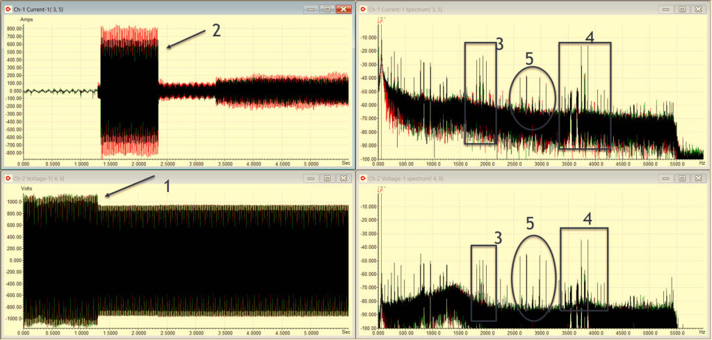
Fig. 3. Current and current spectra top, and voltage and voltage spectra bottom.
As shown in Fig. 4, these conditions continue, even after several minutes. Data collected at other towers under continuous monitoring also show that these types of harmonics/sub-harmonics continue, especially in low-wind conditions and heavy wind gusts. Persistent stresses on the system result, but they vary. This finding adds to the confusion.
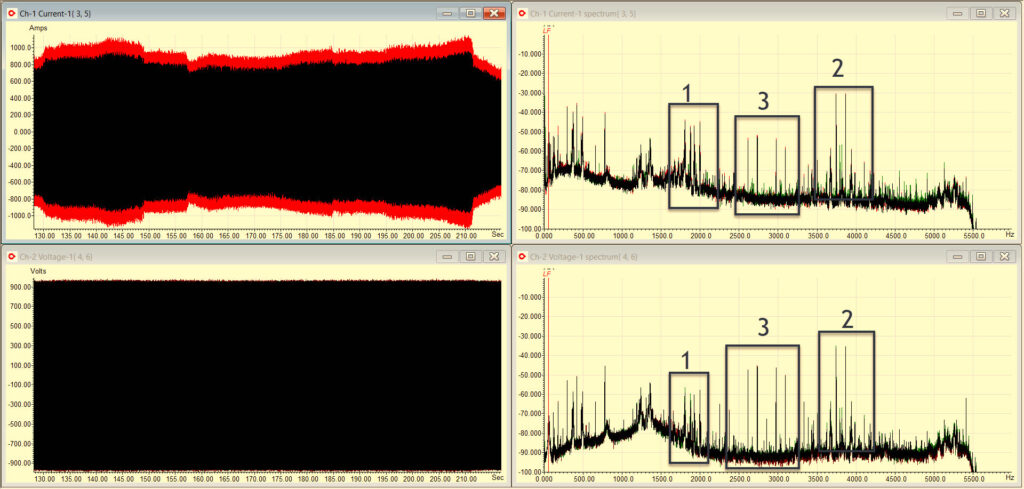
Fig. 4. At the steady point identified as (3) in Fig. 2, the conditions still occur.
Note that wind generation is a long way from customers loads. Long-distance transmission lines have the voltages stepped up well over 138,000 Volts and include either in-line or shunt (parallel) voltage compensation systems to ensure the voltage is steady. The voltage-compensation systems create conditions that, in larger generators, are known to potentially cause Sub-Synchronous Resonance (SSR), an oscillation of the rotor that can occur for a few seconds or longer. Wind sites are exposed to SSR, according to academic papers, but at a much lower value (often around 10%) than what’s seen in large turbines. For example, large steam turbines can see shaft breakage and mechanical failures when the sudden SSR occurs due to faults in the lines.
At the start of our testing, the powertrain and generator were turning with input speeds of 14 to 20 RPM (main shaft) entering the planetary set of the gearbox. Then the speed was increased across low, medium, and high-speed gears and shafts to >1200 RPM (super-synchronous). Figure 5 (on the far-left of the image) shows the impact/shock felt through the entire powertrain when the breaker to the turbine closes. The torque impulses affect the physical gearbox and generator components, while generating an initial electrical impulse that triggers the ferroresonance, i.e., harmonics (Fig. 6), in the core of the transformer (which is supported by the generator-control and voltage-compensation system for the transmission and distribution system). Figure 5 also shows an increase in upper and lower torque, which represents an increase in air-gap torque oscillation (constant loading and unloading of the rotor) as the speed increases.
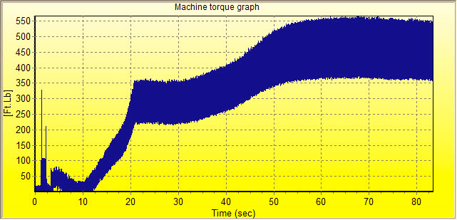
Fig. 5. Torque at startup through run-up of a typical turbine at wind speed of 6.5 m/s and 75 F.
The broadening torque as the speed increases is directly related to the rotor SSR oscillation in air-gap torque.
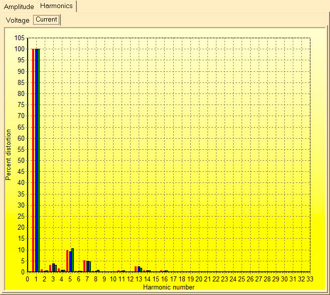
Fig. 6. Current harmonics (odd and even) of the turbine represented in Fig. 5 after steady-state.
While our entire theory is not being presented in this article, the complete set of data across wind-generator manufacturers and, among other things, conditions through the turbine’s electrical system, weather patterns, location, and transmission systems are all taken into consideration. Once the theory has been confirmed, steps can be taken to reduce or eliminate the SSR and ferroresonance. Those steps could have enormous impact on wind turbines globally. At least, in theory. Several solutions are currently being explored.
BEYOND THE ACADEMIC
Without taking a step back to review the system, then, when warranted, stepping back even further, such theories remain the purview of academia. In the case of a systems approach (in any environment or application), real-world observation carries more weight. Reliability engineering also comes into play with the research necessary to discover and define the problem, then find and implement solutions. This type of approach in organizations can have profound effects, with results magnitudes greater than, say, simply replacing a bearing to “get that motor back in operation.”
Part 10 will present another case study related to commercial and industrial applications.TRR
Click The Following Links To Read The Previous Eight Parts Of This Reliability & Maintenance Opportunities Series
“Compressed Air System Efficiency” (Part 1)
“The Benefits From A Holistic Approach” (Part 3)
“Leveraging USDOE’s Energy Assessment Tools” (Part 4)
“Leveraging Industrial Assessment Energy And Productivity Tools” (Part 5)
“Using The P-F Curve And Maintenance Data In Reliability Engineering” (Part 7)
“Taking A Look At The Bigger Picture” (Part 8)
ABOUT THE AUTHOR
Howard Penrose, Ph.D., CMRP, is Founder and President of Motor Doc LLC, Lombard, IL and, among other things, a Past Chair of the Society for Reliability and Maintenance Professionals, Atlanta (smrp.org). Email him at howard@motordoc.com, or info@motordoc.com, and/or visit motordoc.com.
Tags: reliability, availability, maintenance, RAM, wind turbines, wind energy, power transformers, IEC/IEEE 60076-16, Electrical-Signature Analysis, ESA

