In this week’s article, we’ll discuss insulation systems in more detail and the various high-potential (Hi-Pot) testing types and uses for evaluating electric-motor insulation to ground systems. The use of Hi-Pot testing has been around for over a century, much like insulation to ground testing, but with the exception that Hi-Pot is a stress test.
HI-POT TESTING METHODS
There are three basic types of Hi-Pot tests used for testing electrical insulation systems, including the rotating machine, itself, and the cable providing power. These include the AC Hi-Pot, the DC Hi-Pot and the Very Low Frequency Hi-Pot. Each of these has its specific uses, strengths and potential dangers to the operator and equipment being tested.
The AC Hi-Pot test is strictly a pass/fail test performed at a value of twice the nameplate voltage plus 1,000 Volts for new machines applied for one minute. For used insulation systems, the value that is applied should be 125% to 135% of the nameplate value for one minute. Because of the high voltages involved and the difficulty in controlling the charging current, if an insulation defect is discovered, it will generate carbon tracking through the defect and other weak areas of the insulation system, destroying it. The high voltages and potential high currents also generate a possible hazard to personnel conducting the testing.
The DC Hi-Pot test is performed using DC power at a value of twice the nameplate voltage plus 1,000 Volts with the total multiplied by the square root of three for new insulation systems. The new insulation system value multiplied by 65% to 75% for the value tested on used insulation systems. The charging current and leakage current can be monitored during this type of test. This test can also be dangerous to the condition of the insulation system, so an alternate method can be applied referred to as the step-voltage test. In the step voltage test, the voltage is brought up 500 or 1,000 Vdc at a time. The current will briefly spike, then decrease, which relates to the charging current. The current that the value settles on is referred to as the leakage current.
The Very Low Frequency (VLF) DC Hi-Pot test was originally used in cable testing to detect ‘treeing’ insulation systems (tiny fractures). The VLF Hi-Pot applies a 0.1 Hz frequency to the insulation system which ‘excites’ the insulation system. This presents an opportunity for rotating machine testing with the power of an AC Hi-Pot and the safeguard of the DC Hi-Pot.
BASIC ELECTRICAL INSULATION THEORY
The electrical insulation circuit is modeled as a series of parallel RC circuits between conductors and conductors and ground. As changes occur to the insulation system, the values of R and C change. The values of the insulation in each phase are the sum of the turn to turn and coil to coil RC values of each phase. Insulation to ground values are the sum of the insulation between conductors and ground for the complete circuit.
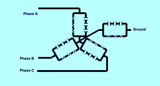
Fig. 1. Insulation model of motor winding system
The capacitance of the electrical insulation is a direct function of the generation of dipoles within the insulation system. As a field is generated across an atom, or molecule, of a dielectric, it will polarize, meaning that the electron orbit of an atom will shift slightly, making one side of the atom more positive and one more negative.
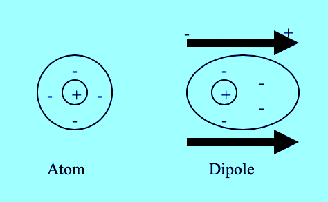
Fig. 2. Generation of a dipole
As current passes through conductors near electrical insulation, the insulation reacts by polarizing the atoms (dipoles) within the insulation. As the dipoles polarize, there is less leakage (capacitance) between the conductors and ground. This also occurs in the insulation system between conductors when there is a difference in potential. In a good insulation system, the polarization of the insulation system occurs in a larger number of atoms. Once the potential is removed, the atoms return to their original state (dipoles randomize).
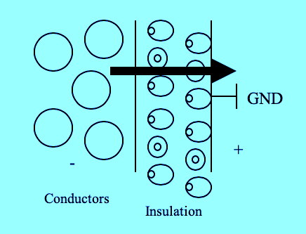
Fig. 3. Dipolar effect of insulation
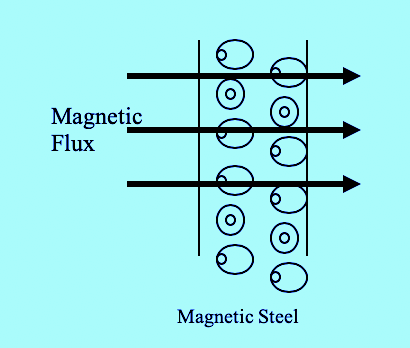
Fig. 4. Magnetic dipoles
The same effect occurs in a magnetic field. The magnetic dipoles of the backiron and teeth of the stator core line up in the direction of the magnetic field. This helps direct the magnetic flux and adds to the strength of the fields within the airgap. The reluctance of the steel to change polarity shows up as hysterisis losses from the field. Once the field is removed, the magnetic dipoles of the steel quickly randomize.
The above descriptions for the polarization of electrical insulation and core steel represent the steady-state application of an applied voltage potential. In an operating three phase system, the effects get far more exciting. As each sinusoidal phase of voltage is impressed across the windings:
√ As the voltage starts from zero, the beginning of the coil energizes, the insulating dipoles between the insulation to ground and the conductors within the coil are forced to polarize.
√ As the voltage continues to rise, the potential at the beginning of the coil is higher than the end of the coil, insulating dipoles continue to polarize and the magnetic dipoles begin to polarize in the direction of the magnetic flux generated by the coils.
√ As the voltage hits its peak at the beginning of the coil, a majority of the magnetic and insulating dipoles associated with the start of the coil have polarized and the ones at the end of the coil continue to polarize. There is a lag in the fields between the beginning and the end of the coil, which causes a potential between conductors to exist.
√ As the voltage begins to decrease, the insulating and magnetic dipoles begin to randomize (move to neutral) at the beginning of the coil and release energy back into the system as the fields collapse. The fields at the end of the coil hit their peak then start to decrease.
√ The voltage approaches zero, then passes into the negative sequence of the sine wave. The dipoles and fields continue to react, but align in the opposite direction (as in a piston action). We will define this action as ‘dipolar spin’ of both the electrical insulation and magnetic steel dipoles.
The high potential of most electric motors forces the changes to the fields and dipoles to happen quickly. As a result, work is performed and heat is generated.
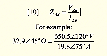
The capacitance of each portion of the circuit is given, at any time, as:
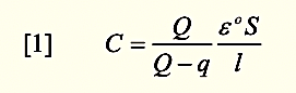
Where an insulator exists between the conductors and conductors and ground. The induced charge, q, increases the capacitance by the ratio Q/(Q-q). The dimensionless ratio q/(Q-q) is a property of the polarizability of the material and is referred to as the electric susceptibility, Xe. At the boundary of each insulation system (conductors, slot, phase, etc.), the boundary conditions are such that:
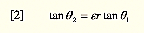
Where εr represents the relative permittivity of the boundary of the insulation surface.
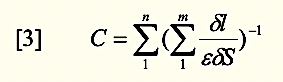
By dividing each phase into tubes and slices, the total capacitance for m slices and n tubes through the system would be:
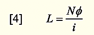
The inductance of the circuit can be calculated as the flux linkage per unit of current, and is represented by the unit Henry (H):
For a motor with n coils, the inductance may be defined:
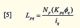
Where Kpq is referred to as the coupling coefficient between two coils (p and q). When p and q are equal, the inductance is termed as self-inductance, when unequal, it is termed mutual inductance.
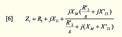
The total impedance per phase as viewed from the stator input terminals is given as [6] where X refers to the leakage reactance (capacitive).
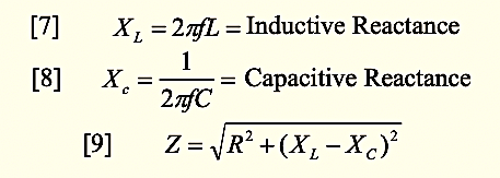
In simpler form, impedance can also be viewed as:
When looking at a balanced system, a wye circuit should appear as in Fig. 5.
Fig. 5. Balanced wye system
The circuit impedance would appear as:
Armed with this information, we can now review the effects of winding related faults on the operation of the motor.
WINDING FAULTS
When a defect occurs in a winding due to a developing short, winding contamination or severely damaged core steel, it effects the electrical properties of the insulation system. In the case of a winding defect, changes to either capacitance or resistance within the insulation system will cause a reactive problem due to changes to the makeup of the insulation system. For instance, in a developing short, the changes to the insulation system cause changes to the capacitance due to changes in how the dipoles are excited (dipole spin). As a result, there are changes to how the insulation reacts in that area, causing a leakage reactance variance and heating due to forcing the insulation to polarize with high applied potential (operating voltage). Winding contamination causes changes to the resistive and capacitive reactance between insulating surfaces, as well.
At design voltage, most defects do not become apparent until a distinct change occurs, which may be represented by a severe current unbalance, nuisance tripping or a direct short circuit. In the case of winding contamination, the end result is the same as a winding short: Either a short between conductors or across the insulation system to ground.
As a result, as faults occur due to thermal deterioration, contamination, moisture absorption or other reactive faults, the circuit impedance will change, slightly, at first, then more dramatic as the fault progresses.
HI-POT METHOD FOR INSULATION TO GROUND STRESS TESTING
The type of testing performed by Hi-Pot testing only evaluates that plane between the conductors and the slot wall of the stator core, or the slot cell wall. They do not detect inter-turn winding faults or developing winding shorts. An additional important requirement in all high voltage testing is ensuring that the winding is clean and dry prior to testing. These conditions, of course, limits the abilities of this type of testing. However, there are a few tricks that can expand their test capability.
All Hi-Pot testing is set up in a similar fashion: If possible, each phase is seperated with each phase not being tested, RTD’s and other coils in the system are shorted to ground. This allows the insulation system between the coils being tested and the other insulation systems to be tested while also ensuring that there are no circulating currents and the leads are away from operators.
While AC Hi-Pot testing is the most dangerous form of testing, the AC applied voltage and current generate some excitation of the insulation dipoles. This gives a more complete pass/fail analysis of the condition of the system. The operator must also ensure that the lead is held rigidly against the conductor prior to applying voltage otherwise the arc that is generated will cause spikes that may cause latent damage to the insulation system. When testing an electric motor in place, the danger to the equipment is even more severe because of the additional surface area of the cabling. Any additional components such as capacitors, variable frequency drives, etc. including current and potential transformers, must be disconnected and grounded to reduce the chance for damage.
With the DC Hi-Pot, the safest approach is the step voltage test. If evaluating an electric motor rated under 600 Volts, step increments at 500 Volts, if above 600 Volts, step the voltage at 1,000 Volts. This reduces the charging current stresses on the insulation system. With the leads of other windings connected to ground (only if you can break the connections between phases) and components, you are also evaluating the condition of the insulation system between those phases as well as the phase being tested to ground. Just as with the AC Hi-Pot, everything should be disconnected if you are testing through the cable system to the motor. In both cases, the leakage current should be trended, this is the current that the meter stabalizes on after the voltage is increased. The trend should be a steady increase and any sharp increase in leakage current before the test reaches the calculated voltage indicates an insulation defect that should be corrected.
The VLF DC Hi-Pot provides a slightly more inclusive test which is handled in the same way as the DC Hi-Pot. The primary difference between the two is that the VLF provides some level of excitation of the insulation system dipoles. This will more closely identify insulation to ground defects.
CONCLUSION
Electrical insulation systems are, primarily, dielectric systems. The purpose of high voltage testing of the ground insulation system is to identify if the system can withstand higher than normal stresses. This type of testing requires the insulation system to be clean and dry, otherwise there is potential for insulation failure directly as a result of the test.
Of the three types of Hi-Pot tests, the AC Hi-Pot provides the greatest danger to the insulation system and personnel, but provides the greatest opportunity to identify defects. The DC Hi-Pot allows the operator to trend the condition of the insulation leakage current when the step voltage test is performed. The VLF Hi-Pot provides many of the strengths of both the AC and DC Hi-Pot tests, with less danger to the insulation system.TRR
Click On The Following Links for Previous Articles In This Electric-Motor Reliability Series
March 28, 2020: “What The Studies Really Said”
April 12, 2020: “Comparing What The Studies Said”
April 18, 2020: “How The Studies Applied to Larger Motors”
May 2, 2020: “A Data Mind-Bender”
May 29, 2020: “Site and Study Findings Compared”
June 13, 2020: “Developing Testing Programs”
June 19, 2020, “High-Voltage Testing”
July 3, 2020: “Testing with Ohm Meters”
July 10, 2020: “Best Practice to Insulation to Ground Testing Methods”
July 25, 2020: “Annex D in IEEE 43-2013
ABOUT THE AUTHOR
Howard Penrose, Ph.D., CMRP, is Founder and President of Motor Doc LLC, Lombard, IL and, among other things, a Past Chair of the Society for Reliability and Maintenance Professionals, Atlanta (smrp.org). Email him at howard@motordoc.com, or info@motordoc.com, and/or visit motordoc.com.
Tags: motor testing, motor windings, motor insulation systems, high-potential test, HI-POT testing, reliability, availability, maintenance, RAM

