As discussed in the July 3, 2020, installment of this ongoing series the insulation-to-ground tester, or Meg-Ohm meter, was also one of the earliest instruments used by technicians to evaluate and troubleshoot insulation systems. That includes electric-motor-insulation systems. In this article, we concentrate on the method outlined in IEEE Standard 43-2013, “The Recommended Practice for Testing Insulation Resistance of Rotating Machinery,” (IEEE 43) and a few additional methods for evaluating findings. We also will be referring to the method as Insulation Resistance (IR) testing.
Editor’s Note: It’s very important to not confuse the use of “IR” in this article
with the standard industry acronym for infrared [IR] thermography
.
INTRODUCTION
The insulation-resistance standard we generally reference within industry is IEEE 43, which went through a major revision in May of 2000. (This updating was done due to the fact that post-1970 insulation systems had gone through a series of changes in chemical makeup.) Newer insulation systems differ greatly from the older systems, including how they react through testing methodologies.
The revised standard drastically changed a number of traditional testing programs for insulation resistance that had been in place for over 50 years, including the polarization index (PI), insulation-to-ground tests, and AC versus DC testing of insulation systems. The 2013 edition went further by identifying different thermal curves for temperature correction based on the insulating materials.
The purpose of the IR reading is to evaluate the condition of the insulation between the conductors in the stator slots and ground. This is done by applying a direct voltage between the conductors (windings) and the casing of the electric motor (machine) and measuring current leakage across the insulation system. The measurement of current and voltage, applied, provide a finding measured as resistance (Ohm’s Law: R = V/I). In the case of an insulation system, the leakage current may be measured in milli- or micro-Amps, with the lower the current reading, the higher the insulation resistance value. These IR readings change over time because of “insulation polarization.” In effect, the insulation system consists of polarized atoms that “line up,” or polarize, with the applied DC voltage. As they polarize, the insulation resistance will increase.
BASIC INSULATION-RESISTANCE TESTING
Straight insulation-resistance testing has been used to troubleshoot and evaluate the condition of machines for more than century, often with disastrous results in the hands of an inexperienced user. There are very clear limitations on the ability of insulation-resistance testing alone to evaluate the condition of an electric motor for operation. Among other things, there must be a clear path between the insulation system and the casing of the machine. Air, mica, or any other non-conducting material between the winding and ground will provide a high insulation resistance. Faults on the end-turns of motor windings also will not provide a clear path to ground, with most winding faults starting as internal winding shorts that might graduate to insulation faults. Thus, great care must be taken when using insulation-resistance testing as a troubleshooting tool.
When performing insulation-resistance testing, the proper method is to connect all leads together, test with the meter for a period of one minute, ensuring that the red test lead (negative) is on the leads and the black lead is on the housing. Once the IR measurement is obtained, it is then adjusted for temperature while the leads are grounded for 4 or more minutes. The values for IR applied voltage and minimum test values can be found in Tables I and II.
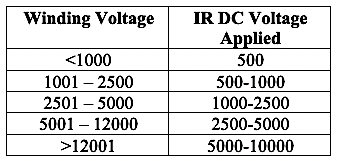
Table I. Insulation Resistance Test Voltage
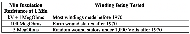
Table II. Insulation Resistance Minimum Values
Several things must be considered when performing insulation resistance from a motor-control center (MCC) or disconnect that’s a distance from the motor under test. For one, if you tie all of the cable leads together and test, due to the surface area under test, it’s possible the readings could be only a few MegOhms. This doesn’t necessarily mean the system is bad, and a few tricks can be used to evaluate the condition of the cable. Additionally, any capacitors or lightning arrestors should be disconnected from the circuit and variable frequency drives (VFDs) or amplifiers must be disconnected from the motor.
First, take each conductor and test between the conductor and ground. If the reading is greater by an order of magnitude then chances are that no problem exists. Next, disconnect the other end of the cable and separate the conductors from each other and ground. At the other end, perform the insulation resistance test between conductors. If the readings are above the minimum, then the insulation resistance of the cable is OK, i.e., acceptable, (however, it does not definitively clear the cable of any potential faults).
The same process can be used on some motors, with the exception of a phase to phase test, unless the internal connections of the motor can be broken, such as in a wye-delta motor or all 12 leads are brought out of the machine. If the phases can be separated, then an insulation resistance measurement can be taken between phases. The results should be above the minimum values shown above.
During these tests, if you are using an analog meter and the needle isn’t steady, or the numbers “dance” around in a digital meter, there’s a strong possibility that moisture or contaminants have gotten into the windings. The bouncing is the result of “capacitive discharge,” or the build-up of the DC energy within the winding that suddenly discharges and then begins to re-charge.
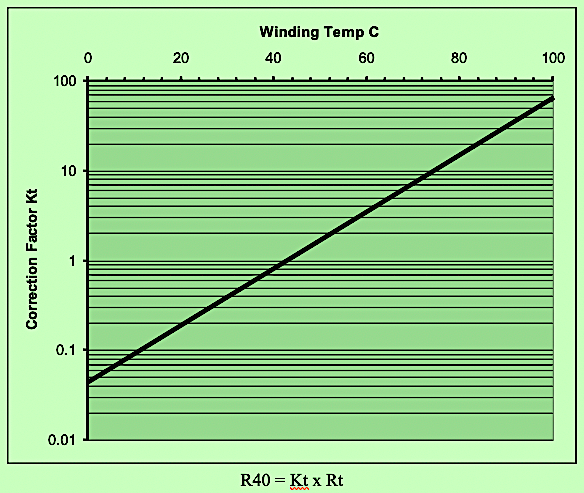
Fig. 1. Insulation-resistance temperature correction
Figure 1 represents the insulation-resistance temperature correction chart for correcting to 40 C. Using this chart, if the winding temperature is 60 C and the insulation resistance was 200 MegOhms, the correction factor (Kt) would be “4,” and the result would be 4 times 200 MegOhms, which would be a corrected insulation resistance of 800 MegOhms.
DIELECTRIC ABSORPTION
The dielectric absorption test (DA) is a ratio of the 60-sec. IR reading to the 30-sec. reading. As shown in Fig. 2, the value at position A is divided by the value at position B. In a good insulation system, the IR will increase as a curve which will start fairly steep then will plateau, depending upon how fast the insulation system polarizes. Pass/Fail criteria can be found in Table III. However, in insulation systems manufactured after 1970, it is not uncommon for insulation systems to polarize rapidly. Moreover, insulation systems with a temperature-corrected 1-min. reading greater than 5,000 MegOhms may show a low value. In these instances, the test results should be used for trending only (and per the new IEEE 43, the test results must be corrected for temperature).
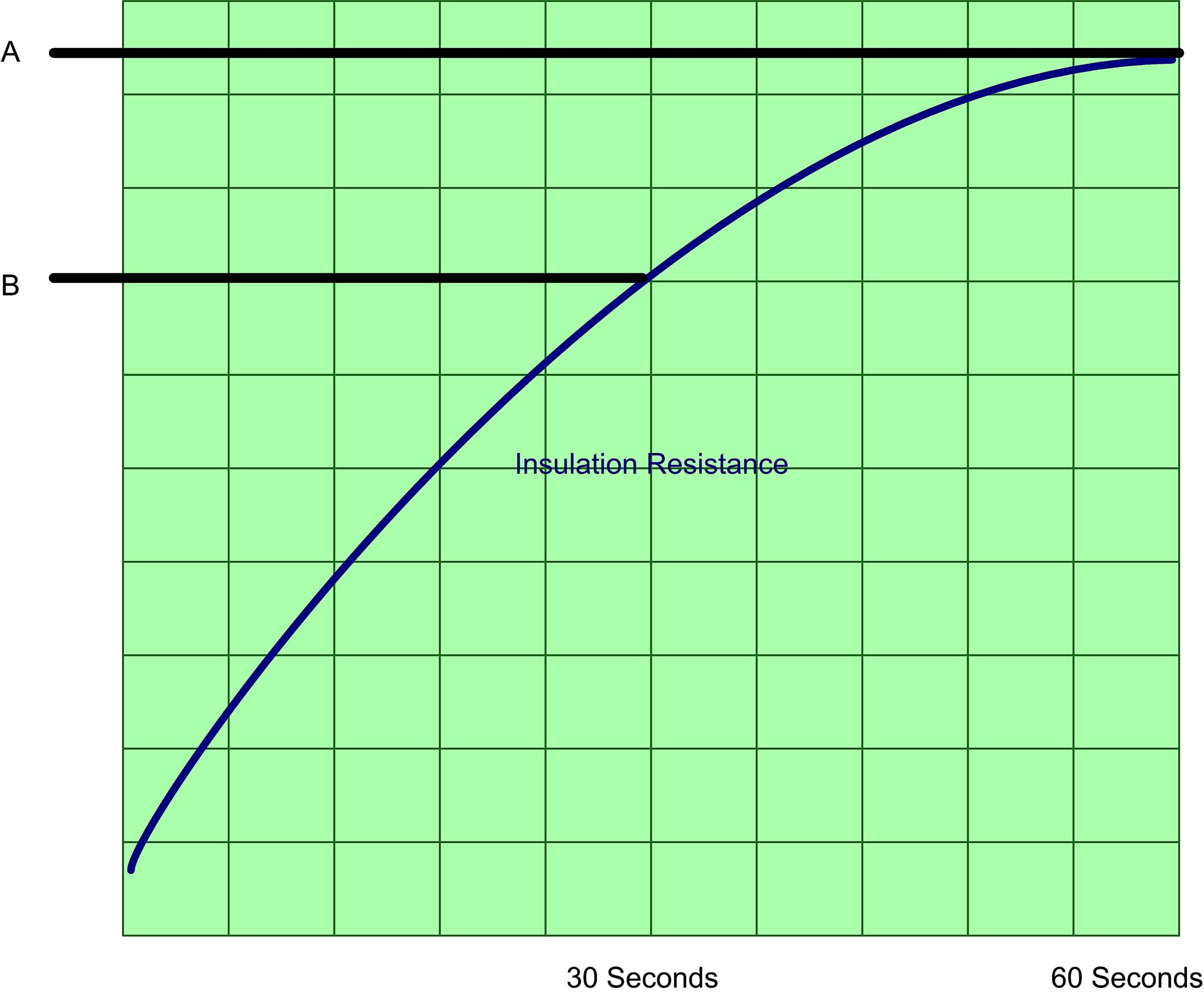
Fig. 2. Dielectric absorption (DA)
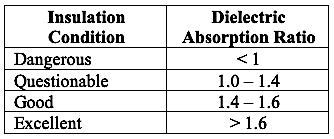
Table III. Dielectric Absorption Chart
POLARIZATION INDEX
The polarization index (PI) is the ratio of the 10-min. to 1-min. insulation resistance test. As shown in Fig. 3, the result is the value at position A divided by position B. In a good insulation system, the IR will increase as a curve which will start fairly steep then will plateau, depending upon how fast the insulation system polarizes. Pass/Fail criteria can be found in Table IV. However, in insulation systems manufactured after 1970, it’s not uncommon for insulation systems to polarize rapidly and insulation systems with a temperature corrected one minute reading greater than 5,000 MegOhms may show a low value. In these instances, the test results should be used for trending only (and per the new IEEE 43, the test results must be corrected for temperature).
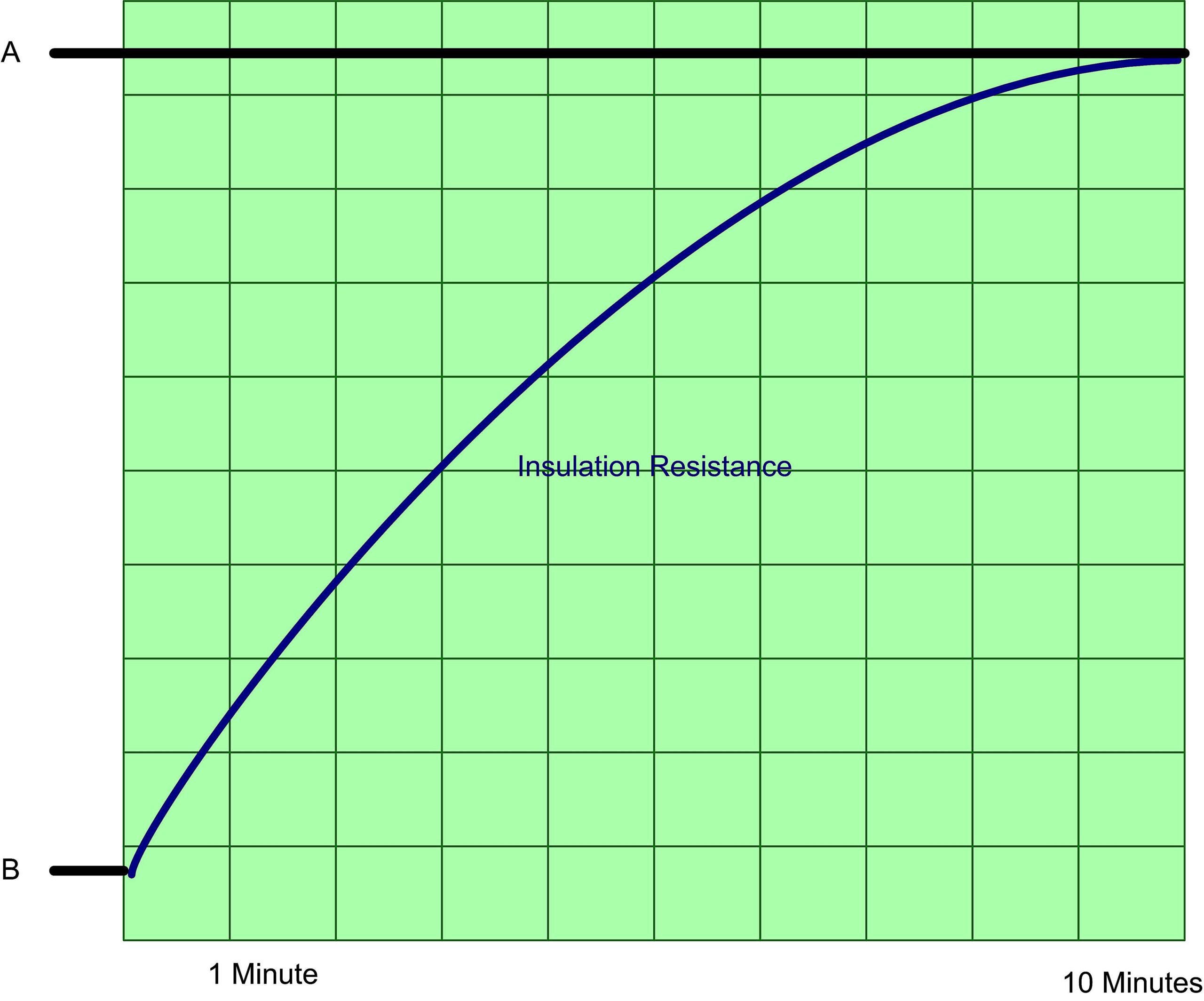
Fig.. 3. Polarization index (PI)
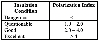
Table IV. Polarization-Index Values
Using the PI, the user should watch the needle if the meter is analog. If the needle bounces as it increases, then it represents capacitive discharge and an impending insulation problem such as contamination. If the meter graphs the PI as a chart, the user should review the data to see if there are any downward spikes or the graph shows a decreasing value across the ten minutes. This would also indicate insulation resistance defects.
CONCLUSION
A common method for evaluating the condition of electric motors is insulation resistance testing. The most common methods of IR testing are outlined in the IEEE Standard 43-2013 and include the 60-sec. test, the dielectric absorption and the polarization index test. Each of these tests are used to evaluate only the portion of the insulation system between the motor winding and the frame of the electric motor.
In post 1970 machines, insulation systems tend to polarize rapidly and systems with values over 5,000 MegOhms should only be trended when using DA and PI. The insulation charging can be viewed to see if capacitive discharges, which indicate winding contamination or insulation degradation, are occurring. However, the insulation- resistance test is a powerful tool when used in conjunction with other testing methods.TRR
Click On The Following Links for Previous Articles In This Electric-Motor Reliability Series
March 28, 2020: “What The Studies Really Said”
April 12, 2020: “Comparing What The Studies Said”
April 18, 2020: “How The Studies Applied to Larger Motors”
May 2, 2020: “A Data Mind-Bender”
May 29, 2020: “Site and Study Findings Compared”
June 13, 2020: “Developing Testing Programs”
June 19, 2020, “High-Voltage Testing”
July 3, 2020: “Testing with Ohm Meters”
ABOUT THE AUTHOR
Howard Penrose, Ph.D., CMRP, is Founder and President of Motor Doc LLC, Lombard, IL and, among other things, a Past Chair of the Society for Reliability and Maintenance Professionals, Atlanta (smrp.org). Email him at howard@motordoc.com, or info@motordoc.com, and/or visit motordoc.com.
Tags: motor testing, insulation-resistance testing, Ohm meters, reliability, availability, maintenance, RAM, IEEE

