This article is part of a continuing series that began with discussions of IEEE and EPRI large-electric-motor studies and what those studies considered “excellent maintenance.” At this point, the series has moved beyond the emphasis on large motors and, starting with the June 19, 2020, installment on high-voltage methods, has begun highlighting a variety of testing methods. This article looks at today’s Ohm-meter technology.
INTRODUCTION
The use of the Ohm meter has been around long before AC induction motors. In these modern times, we have instruments that can measure extremely high resistances and those that can measure extremely low resistances. In this article, we will concentrate on Ohm meters, milli-Ohm meters and micro-Ohm meters. The proper selection of which one to use for analyzing your machines, within the capabilities of simple DC resistance testing, is extremely important.
SELECTING THE RIGHT TOOL
There are both analog and digital Ohm meters, just as with other basic measurement instruments. In the past, analog Ohm meters provided excellent means of measuring the condition of machines with modern digital instruments providing additional accuracy.
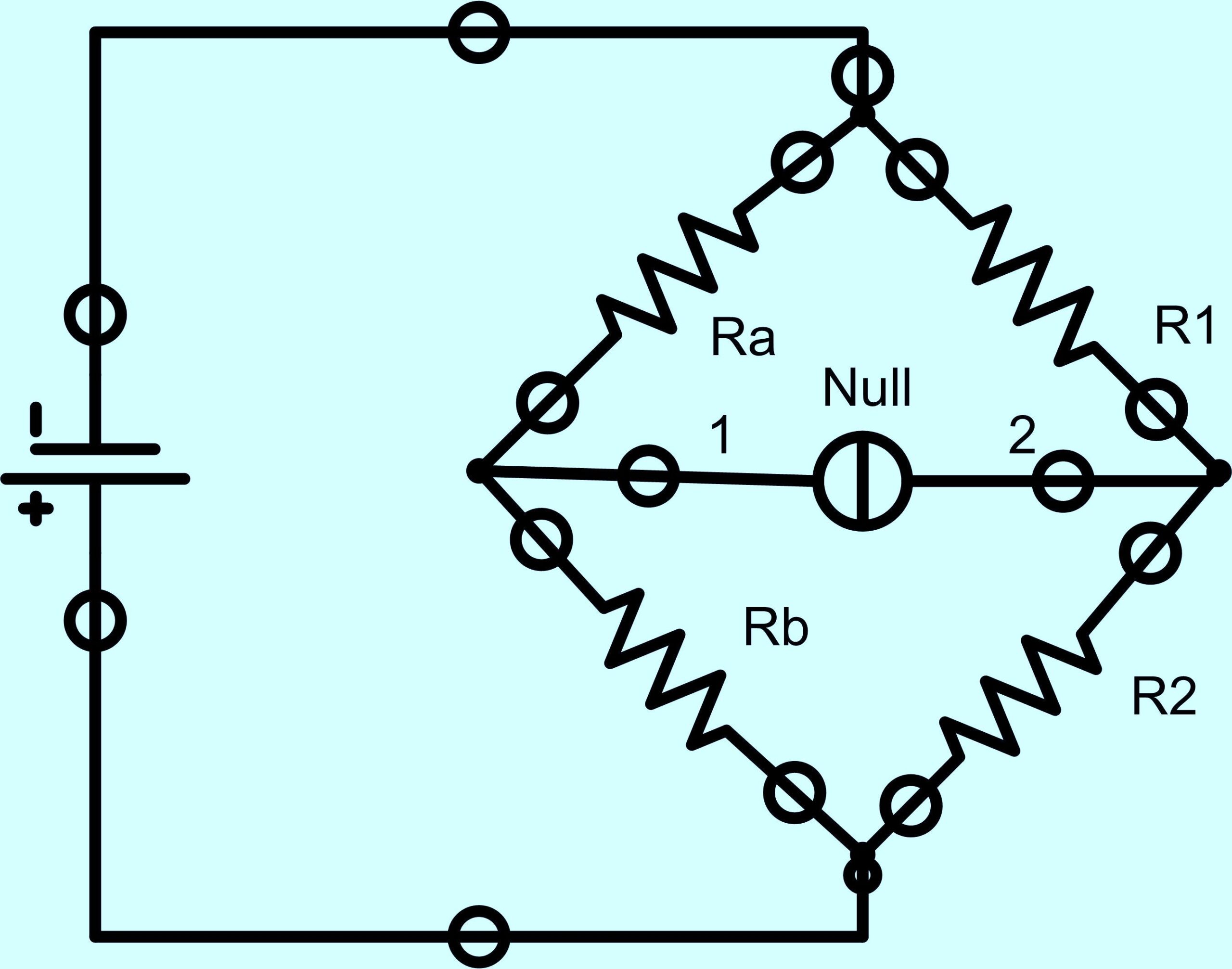
Fig. 1. Wheatstone Bridge
One of the issues, when taking resistance measurements on electric motors has to do with the resistance of the electric motor circuit. A rule of thumb, on machines under 600 Volts AC, is that the resistance will become less as the horsepower increases. For instance, an average one horsepower motor may have a resistance of 40 Ohms while an average 100 horsepower may have a resistance of 0.010 Ohms. Electric motors over 1,000 Volts AC will tend to have resistances over a few Ohms.
The type of measurement method used by the instrument will be of importance as to the accuracy of the test. We will cover the basic circuits, the Wheatstone bridge, the Double Kelvin Bridge and the Four Wire Kelvin Bridge.
The Wheatstone bridge (Fig. 1) works by comparing resistances and a null balance meter to compare DC voltage in the circuit being tested. Basically, when the voltage between point 1 and the negative side of the battery is equal to the voltage between point 2 and the negative side of the battery, the null detector will show a zero voltage, and the bridge can be considered balanced. With the circuit, the state of balance is solely dependant upon the ratios of Ra/Rb and R1/R2. When used to measure an unknown resistance, the unknown is connected in place of Ra or Rb. The remaining three resistors are precision and any of these resistors can be replaced or adjusted until the bridge is balanced. Once the balance is obtained then the unknown value can be determined by the ratios of the known resistances. The accuracy of the meter depends upon the stray voltages that exist in the conductors that affect the null detector which result from wire and connection resistances within the bridge, and the accuracy of the precision resistors.
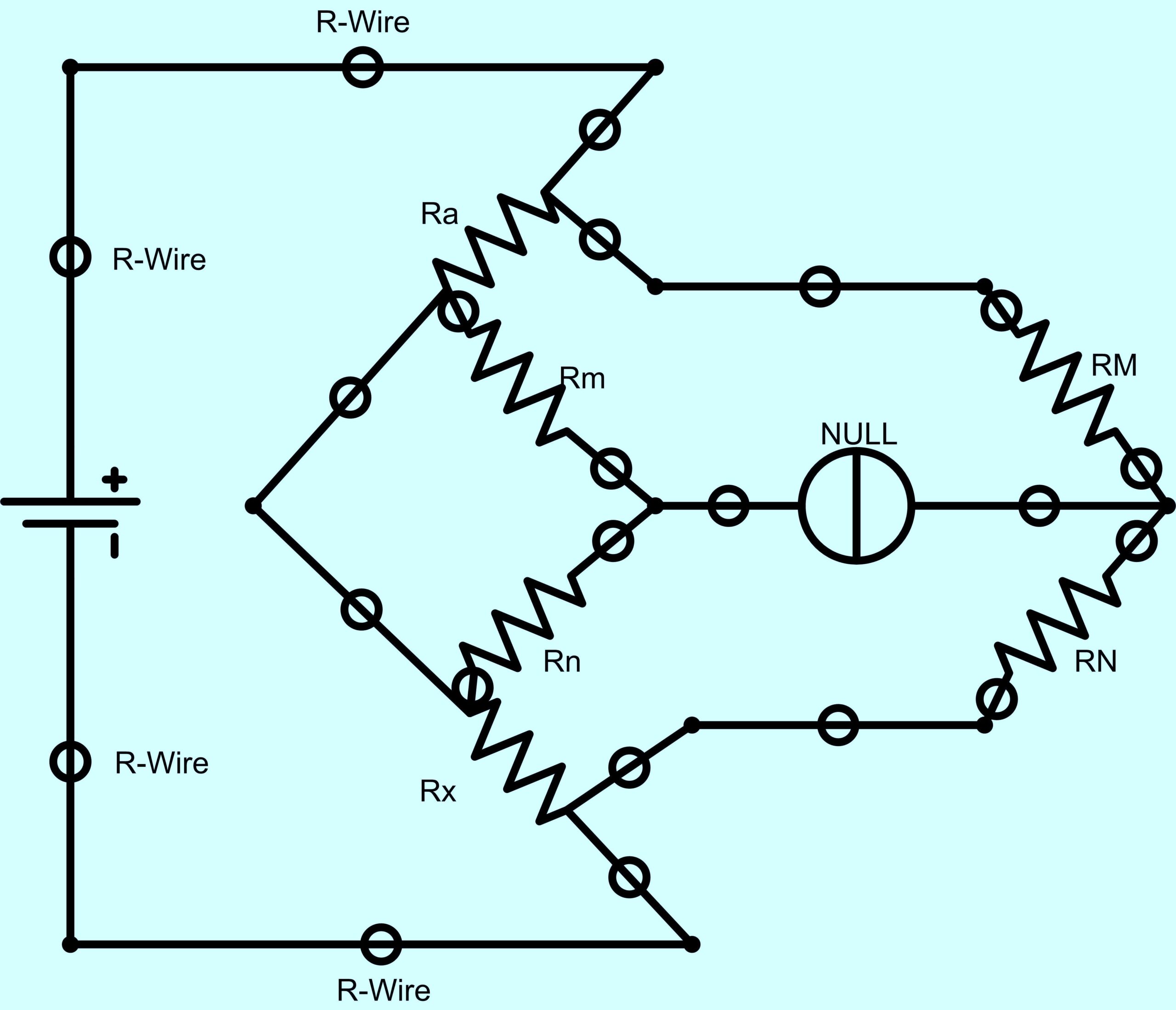
Fig. 2. Double Kelvin Bridge
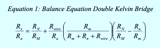
The Double Kelvin Bridge (Fig. 2) is a modified version of the Wheatstone bridge. It compensates for the stray voltages within the circuit, and the circuit being tested, due to the wire and connection resistances. With the ratio Rm/Rn set equal to the ratio of RM/RN, Ra is adjusted until the null detector indicates balance. The actual balance equation for the Double Kelvin Bridge can be found in Equation 1. The accuracy of this type of bridge is at least 0.05% and usually used for circuits measuring in the milli-Ohm range.
The next type is the 4-Wire Kelvin Bridge (Fig. 3), which uses Ohms Law to determine the resistance. Its particular application is in circuits where there are long test leads and significant stray voltages. It also allows for very low (micro-Ohm) measurements with a high degree of accuracy. Figure 4 shows a more common Kelvin circuit, in which the losses and inaccuracies due to an Ammeter are compensated for by using a calibrated shunt resistor that also sets the accuracy of the instrumentation.
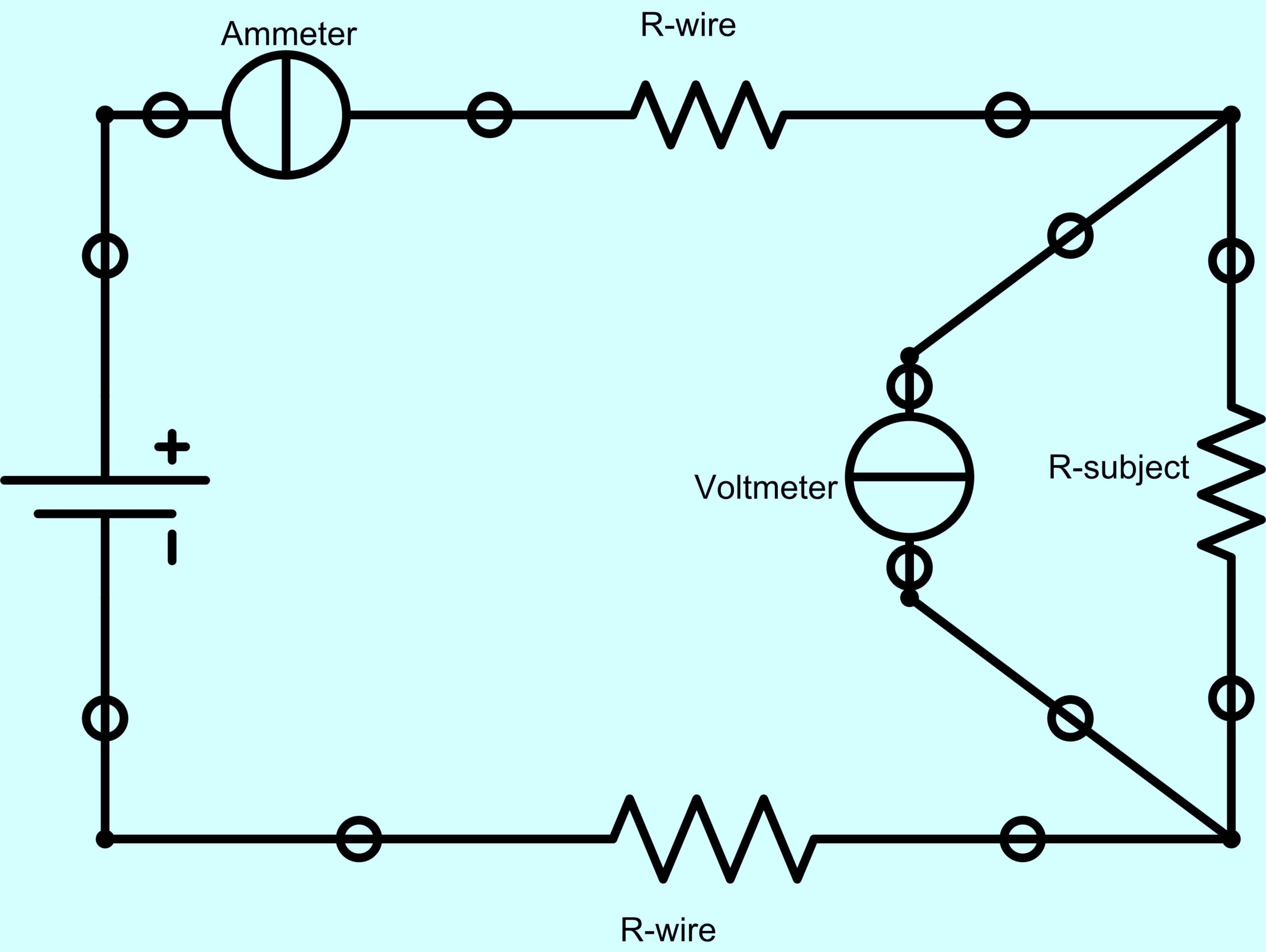
Fig. 3. Basic 4-Wire Kelvin Bridge
In digital instrumentation, the circuit board is used in part to provide a portion of the bridge with the logic providing the adjustment for the null circuit.
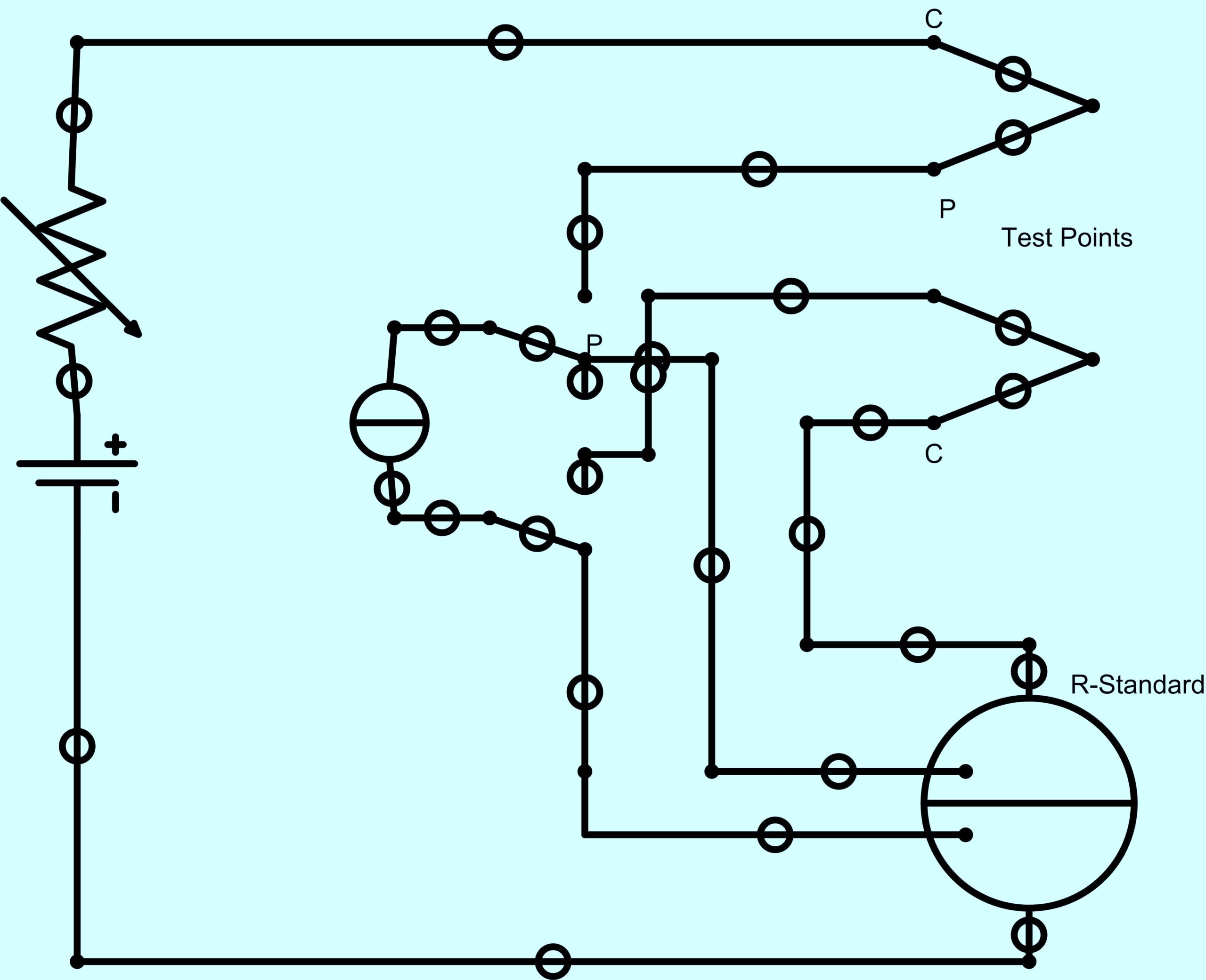
Fig. 4. 4-Wire Kelvin Bridge
Some instruments will use the 4-Wire Kelvin Bridge for very accurate micro-Ohm measurements and others will compensate for circuit resistance, using a Double Kelvin bridge by measuring through the test wires first, before measuring the circuit under test.
OHM METER CONSIDERATIONS
There are a number of things to consider when using an Ohm Meter to test an electric-motor circuit. These considerations include:
1. Voltage present on the circuit when testing from a Motor Control Center (MCC), or disconnect. This voltage may include Electro-Magnetic Induction (EMI);
2. Temperature of the motor windings;
3. Connections through the circuit, as well as differing lengths of conductors, when testing from an MCC may cause an unbalance.
and/or
4. Whether or not there are series or parallel resistances in the circuit.
In precision instruments, EMI or other voltages present in the circuit will cause readings to be non-repeatable. This can be observed if the measured value does not ‘settle’ during the measurement.
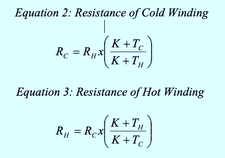
The temperature of the motor windings must be compensated for when trending measurements. If you are troubleshooting an electric motor, comparing phase to phase does not require compensation. The reverse can be performed, as well, in order to determine the winding temperature of a motor, if an original temperature and resistance are known.
In both of the formulae below (Equations 2 and 3), the K (constant) is based upon the material being tested, with Aluminum = 225 and Copper = 234.5, and RC being the resistance of the winding cooler than during the test and vice-versa.
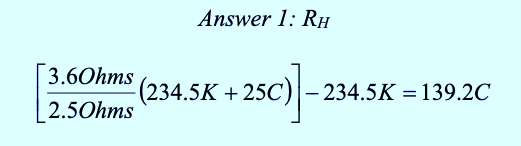
For example: If a copper motor winding was measured as 2.5 Ohms at 25 C, the technician later tests the motor at 3.6 Ohms. What is the winding temperature?
The next consideration is whether or not the windings are in series or parallel (see Equations 4 and 5). This will affect the total resistance such that, for instance, if the induction motor is connected in series for the high-voltage connection or parallel for lower voltage connections. It is also important to understand if there are multiple wires in parallel, even of different resistances, should one or more be broken.
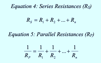
If a circuit has a combination of series and parallel circuits, solve for the parallel circuits individually, then solve for the system as a series circuit.
TROUBLESHOOTING WITH OHM METERS
When testing from phase to phase on an electric-motor circuit, you must connect the motor for operating voltage. This way you are testing three equivalent circuits. Alternately, you may be testing from the MCC or a disconnect from phase to phase.
The most accurate way to test an electric motor is to ensure that you are using an instrument capable of testing out to 0.001 Ohms, or to 0.0001 Ohms for higher horsepower 460-Volt motors. It should be noted that the low-voltage and high voltage resistances of the motor will be different.
In the case of resistive unbalance, the losses measured in Watts will relate to the resistance of each circuit and the amount of current. Additionally, spot resistance, such as with a loose connection, will cause local heating. Both situations relate to Equation 6.
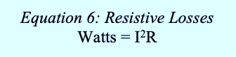
If a circuit is carrying 100 Amps and a connection has a resistance of 0.1 Ohms, then the loose connection will generate 1002 x 0.1 Ohms = 1000 Watts, or 1kW, at that point.
Depending upon the standard used, the allowable Resistive unbalance, from phase to phase, should be no more than 2% at the motor. Unbalances greater than this amount, or unbalances that have increased, will often relate to loose connections, direct shorts or broken conductors within the motor or conductors.
CONCLUSIONS
The primary use for resistance measurements in electric motors is to determine if there is a direct short, loose connections or broken conductors. The measurements can also be taken and corrected for temperature to provide valuable information such as winding temperature, or if there are other changes. The impact of loose connections can also be determined. However, the correct instrument must be selected for the application in which the instrument used must be able to measure resistance at least one decimal point greater than the circuit being tested.
In the next part of our series, we’ll cover the use of insulation-to-ground measurements, often referred to as MegOhm testing for induction machines. This will include information on the latest version of the IEEE Standard 43, the “IEEE Recommended Practice for Testing Insulation Resistance for Rotating Machinery.”TRR
Click On The Following Links for Previous Articles In This Electric-Motor Reliability Series
March 28, 2020: “What The Studies Really Said”
April 12, 2020: “Comparing What The Studies Said”
April 18, 2020: “How The Studies Applied to Larger Motors”
May 2, 2020: “A Data Mind-Bender”
May 29, 2020: “Site and Study Findings Compared”
June 13, 2020: “Developing Testing Programs”
June 19, 2020, “High-Voltage Testing”
ABOUT THE AUTHOR
Howard Penrose, Ph.D., CMRP, is Founder and President of Motor Doc LLC, Lombard, IL and, among other things, a Past Chair of the Society for Reliability and Maintenance Professionals, Atlanta (smrp.org). Email him at howard@motordoc.com, or info@motordoc.com, and/or visit motordoc.com.
Tags: motors, drives, electrical systems, motor testing, Ohm meters, reliability, availability, maintenance, RAM, EPRI, IEEE

