
In our investigative process, we usually return to subs and transformers for data after we do a walkthrough survey. However, in this article, we’re jumping out of order and looking at the data that we will end up gathering at the end of our survey. As we progress through the survey, it’s important to be mindful of the type of information that we need and how that data will relate to our investigation. Our jumping ahead also provides, by way of gathered data or anecdotally, a better understanding of the types of electrical- and electrically-driven-equipment issues at the site.
Safety is critical when reviewing a site, especially if there has been limited access to switchgear and other components. When we do access cabinets to gather electrical data, we will approach the low-energy control-side when possible. Not only does this avoid equipment outages, but it also reduces the chance for arc flash. The examples in Fig. 1 and Fig. 2 show a location where we were gathering data from the back of low-voltage/low-energy analog voltage and current displays.
No work had been done on this switchgear in quite a while, and the 2.5-inch square piece of metal (Fig. 2) had fallen off the top of the relay in the cabinet (Fig. 1). Based on the configuration of the cabinet, this object would have had a path onto the top of the disconnect.
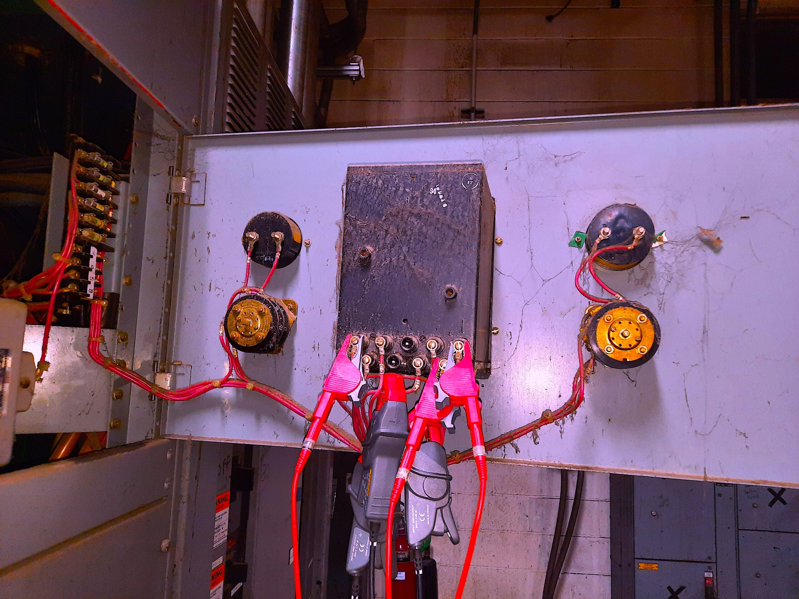
Fig. 1. Back of low-voltage and low-energy meters and relays.
The object shown in Fig. 2 was on top of the relay.
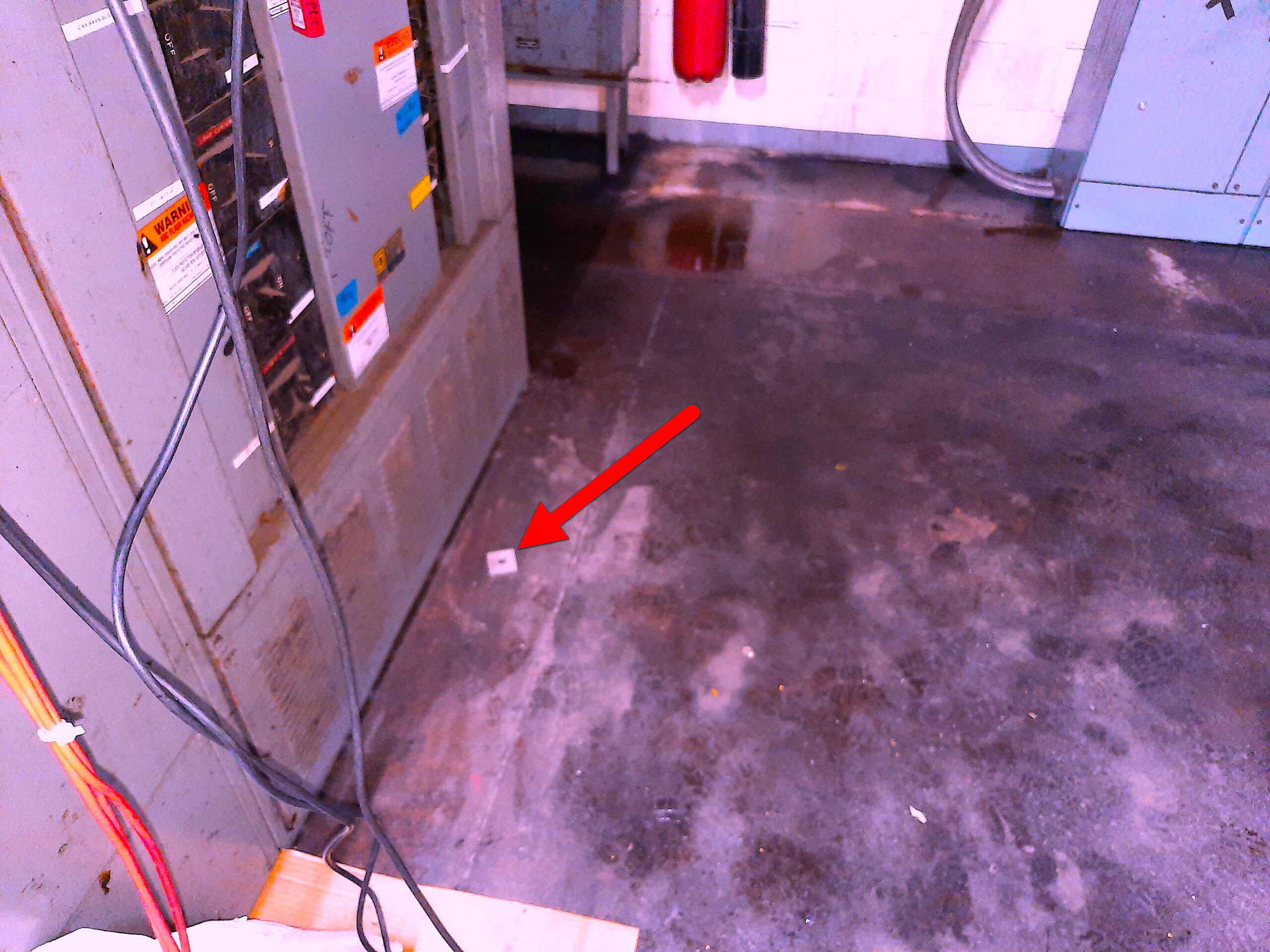
Fig. 2. The metallic object and where it landed. Loose objects
and tools left in switchgear and electrical cabinets
are a primary cause of arc flash.
Opening a cabinet requires experience and training. For instance, when opening the cabinet to collect data the ability to review drawings to ensure that there are either no interlocks or alternate locations for collecting data when interlocks exist. When doors are open it, must be done carefully to not disturb any loose objects. Conditions such as those shown in Fig. 1 and Fig. 2 also serve to remind us why we need to wear appropriate PPE, even when working in Class 0 sections of live electrical or de-energized, systems. Whenever possible, site electricians should be the ones to access cabinets, as they would have experience with the systems and how the cabinets are configured.
The current data collected from the back of the relay in Fig. 1 is found in Fig. 3; the current from one of the ground leads is found in Fig. 4. By reviewing the waveshapes, the pattern in ground (or neutral) can assist in determining if the current is induced in cable runs or conduit.
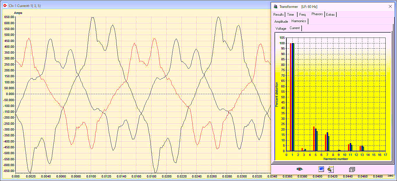
Fig. 3. Three phases of current from CT and harmonic data (THDc).
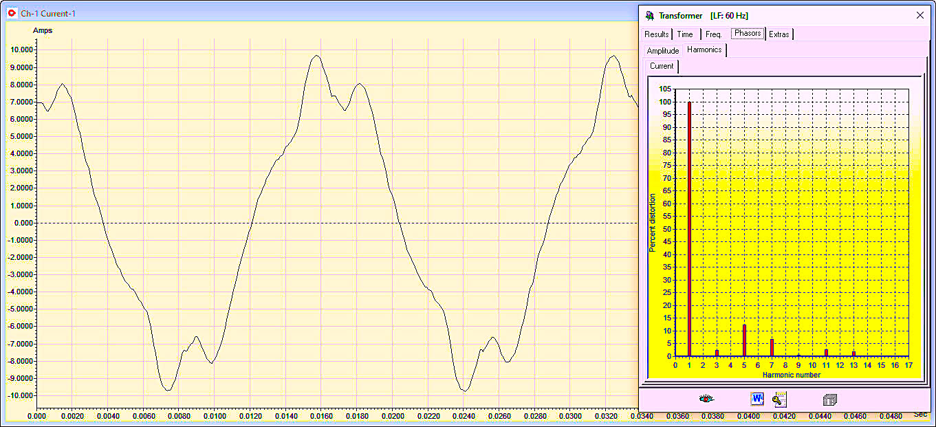
Fig. 4. Ground current and harmonic distortion. Note that the shape
of the ground current is similar to the three phases.
As noted in Fig. 3 and Fig. 4, the patterns are similar, which means that the ground current, in this case, is most likely the result of the ground cable running alongside one or two of the power cables. When bundled as part of a multi-conductor cable or shielded cable there is usually less current present in ground leads in these conditions.
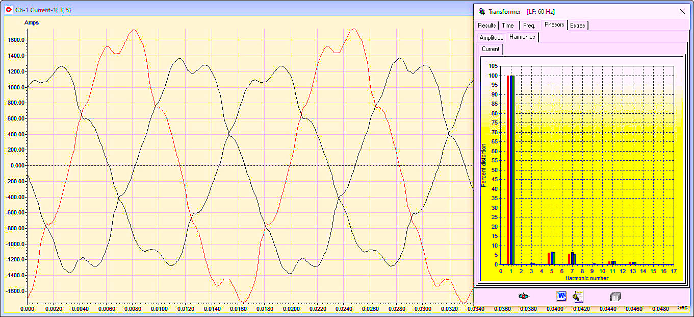
Fig. 5. Current collected at another switchgear.
Patterns such as these are found in systems that provide
lighting and variable frequency drive (VFD) applications.
Data collected from ground and neutral in the cable tray in Fig. 6, appears as shown in Fig. 7. In transformers with center-tapped grounds and neutrals, these currents add up and generate additional loads. Correcting these conditions increases the capacity of the associated transformers, as well as reduces the impact of ground/neutral noise affecting electrical and electronic systems. Electronic systems, including PLCs, variable frequency drives (VFDs), computers, and other systems use ground as a reference.
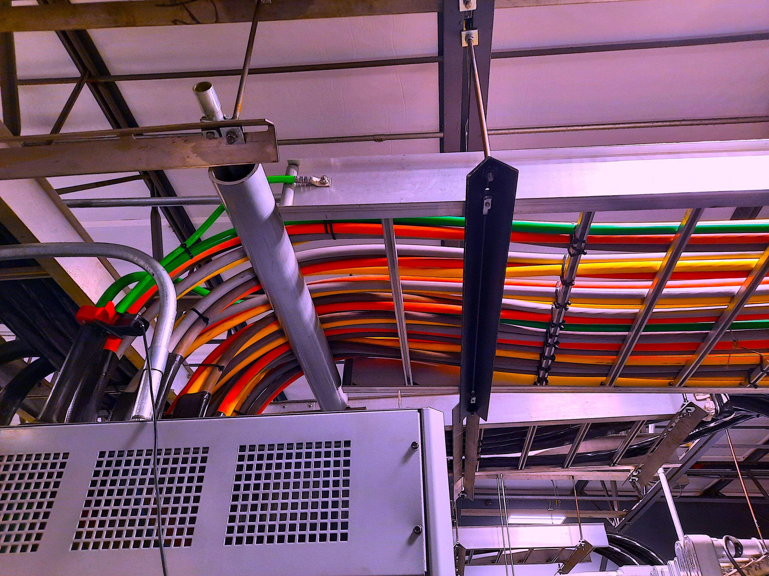
Fig. 6. Location of data collection for ground (green conductors)
and neutral (grey conductors). Note that they are each placed
randomly in the cable tray with power conductors.
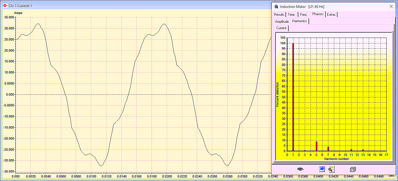
Fig. 7. One of the ground conductors from Fig. 6. Note that the
shape is similar to the phases in Fig. 5.
During our survey, the identification of systems that generate harmonics are noted, as are the amounts of noise and current (and voltage/watts, when applicable) in branches. Mitigation of these conditions can be in the form of corrective actions related to placement of cables; reduction of noise through ground and neutral filters; and power-harmonic active or passive harmonic filters. The reduction in harmonics will impact energy consumption, production throughput, and reliability impact which we will discuss elsewhere.
In Part VI we will discuss the Motor Control Center (MCC) walkdown.TRR
In Part V, we’ll dig deeper into a facility to see what the impact of the PCC is as we develop our story.TRR
Click The Following Links To Read Previous Installments In This Series
ABOUT THE AUTHOR
Howard Penrose, Ph.D., CMRP, is Founder and President of Motor Doc LLC, Lombard, IL and, among other things, a Past Chair of the Society for Maintenance and Reliability Professionals, Atlanta (smrp.org). Email him at howard@motordoc.com, or info@motordoc.com, and/or visit motordoc.com.
Tags: reliability, availability, maintenance, RAM, electric motors, electrical-infrastructure review, energy efficiency, industrial-energy assessments

