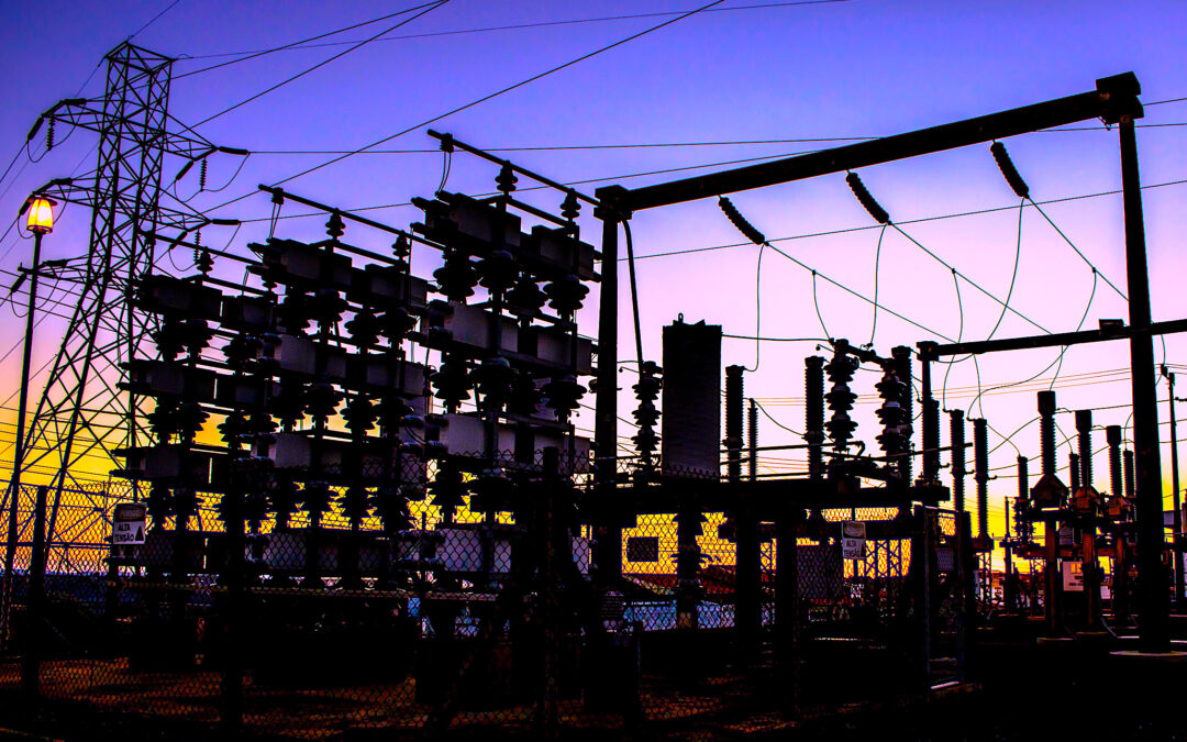
The Point of Common Coupling (PCC) is the place where the electrical responsibility changes from the utility to the customer. Within the standards, the utility has responsibilities for power quality as does the customer for how its equipment and loads impact the power at the PCC. In this second series installment, we are discussing a few of those responsibilities and how they affect the plant, surrounding utility customers, and the utility itself, with an emphasis on IEEE and related USA standards.
The primary standard that covers power quality in the U.S. is IEEE 519, “IEEE Recommended Practice and Requirements for Harmonic Control in Electric Power Systems.” The current published version is from 2014, with updates coming in the 2022 version. The updated version has been voted on and comments are being cleared. This version addresses voltage harmonic distortion at the PCC and has been expanded to apply to internal loads within a facility, something that wasn’t covered in the original (2014) version. In this case, based upon the primary voltage supplied, harmonic limits are placed with the intention of protecting other parts of a plant or local utility grid. In effect, the purpose is to reduce the impact that one energy user has on surrounding users and the utility grid and power generation.
At levels allowed on the local grid, when we add other facilities that are also using non-linear loads from electronic ballasts to variable frequency drives (VFDs), computers, servers, production controls, IoT devices, etc., depending on how stiff the local grid is, we end up infecting each other with poor power quality. In a stiff power system, one with plenty of capacity and newer components, the impact between facilities is not significant. If the system is soft, it is heavily loaded, and the system is tuned to resonate harmonic defects and other poor electrical conditions, such as sags, surges, impulses, lightning strikes, low true-power factor, and other conditions. The utility attempts to compensate for some of these conditions locally and on the bulk grid, as well with generation facilities providing additional voltage compensation.
IEEE 519 also identifies the voltage distortion limits for line to neutral, which in less than 1000 Volt systems (ie, 460 Volt) that in-plant have a maximum 5% individual voltage harmonic and 8% total harmonic distortion. If a facility is using 2,300, 4,160, and 12.4kV systems, the limit is 3% individual and 5% THD (up to 69kV). The utility primary often will be 12.4kV or 13.8kV. However, if the customer and the utility are looking at the high-voltage side of the PCC, it is difficult to determine where the voltage harmonics are coming from, as voltage is primarily supply-related. Unfiltered VFDs and other unfiltered systems will impact both voltage and current.
What’s the impact of harmonic content in voltage and current? Standing harmonics are often referred to as the “3rd harmonic” and multiples starting at the 9th. This chops the top of the voltage or current sine wave and shows up in neutral and ground, according to literature, although the 5th and 7th harmonics are also found in these locations in field measurements.
The 5th and 7th harmonics come from three-phase systems and the multiples start based upon the power electronics. So, a system that has 6 incoming SCRs (converters) would have 5th and 7th; if the system has 18 SCRs (an18-pulse inverter), they would be 17th and 19th.
The 5th harmonic is “counter-rotating” in that it wants to change the direction of motor rotation, and the 7th is a “pro-rotating” harmonic that wants to speed the direction of motor rotation. When you add these harmonics together, you have a stationery and counter- and pro-rotating fields that all produce heat. This, in turn, can cause failures due to heating of electrical systems, including electronics, transformers, motors and generators.
Harmonic content is corrected using filters. These can be passive filters that use inductors for current and capacitance for voltage distortion. Passive systems are normally designed to be “high-pass” filters that can be connected on the power side to correct harmonics and on ground or neutral to reduce losses.
The importance of filtering ground and neutral currents is primarily to control the ground/neutral reference for equipment and reduce energy losses through this circuit, resulting in reduced electrical costs. Additionally, control of ground/neutral reduces loading on the associated transformers.
The other method for controlling power harmonics is use of active harmonic filters, which introduce signals 180 degrees from the harmonic content, negating harmonics throughout the system. We’ll explore some of these options in upcoming articles related to corrective actions.
From a design standpoint, the original IEEE Std 493, commonly referred to as the “IEEE Gold Book,” or “IEEE Recommended Practice for the Design of Reliable Industrial and Commercial Power Systems,” has been converted to standards known as the “3001” series. The plant-reliability group of standards has been converted to the “3006” series, and includes IEEE Std 3006.2, “Recommended Practice for Evaluating the Reliability of Existing Industrial and Commercial Power Systems.”
In the next installments of this article series, we’ll discuss how to approach an electrical-infrastructure assessment.TRR
ABOUT THE AUTHOR
Howard Penrose, Ph.D., CMRP, is Founder and President of Motor Doc LLC, Lombard, IL and, among other things, a Past Chair of the Society for Maintenance and Reliability Professionals, Atlanta (smrp.org). Email him at howard@motordoc.com, or info@motordoc.com, and/or visit motordoc.com.
Tags: reliability, availability, maintenance, RAM, electric motors, energy efficiency, electric-vehicle charging stations


