Popular topics around the renewable-energy community include interaction of inverter-connected power sources to the grid and the impact on components such as transformers (in particular, step-up transformers). One of the concerns with wind and solar-based step-up transformers has been their excessive thermal gassing, which is the direct result of being connected to electronic systems that tend to fall on the lower end of the power curve. Here, we’re focusing on these issues in utility-scale solar-based units.
Click The Following Links For The Previous Articles In This Series
The first thing to remember is that transformer sizing is critical: A lightly loaded one can be more susceptible than a heavily loaded unit to ferroresonance and harmonic heating, both of which increase the presence of explosive dissolved gasses (including hydrogen). The concern is so serious and widespread that standards covering utility and large transformers specifically exclude renewable-energy transformers from their dissolved-gas tables. (See “Reliability & Maintenance Opportunities: (Part 9) ‘Bigger Picture’ Case Study” | The RAM Review).
What’s interesting about utility-scale, solar-generation transformers is the fact that we are usually dealing with two primary (low-voltage) windings and one secondary (high-voltage) winding (Fig. 1), with both primaries fed by separate inverters taking the DC voltage from the panels. Unbalanced loading of the primary will cause circulating currents in the transformer core, resulting in increased heating as well as unbalances to the secondary high voltage part of the transformer.
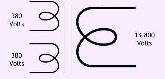
Fig. 1. Solar transformer representation with dual primary low-voltage windings
and a single secondary high-voltage winding.
Figures 2 and 3 show that the inverters feeding half of the primary in this solar transformer carry high 3rd harmonics and operate at a switching frequency of about 2kHz (indicated by the high-voltage spectral peak with sidebands and a harmonic of this frequency with high sidebands). For the example shown in Fig. 4, the transformer is lightly loaded on half of the primary. The second half of the primary carries much lower harmonics (Fig. 5). And, although that half of the primary carries a heavier load (see Fig. 6), the resonance in the transformer (Fig. 7, Point 3) versus that in the other primary surrounding 2kHz (Fig. 3, Point 3), is much higher.
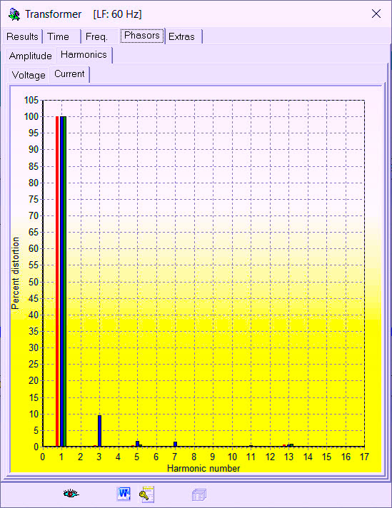
Fig. 2. High current THD at 3rd harmonic Phase B,
with smaller Phase B harmonics in the 5th and 7th.
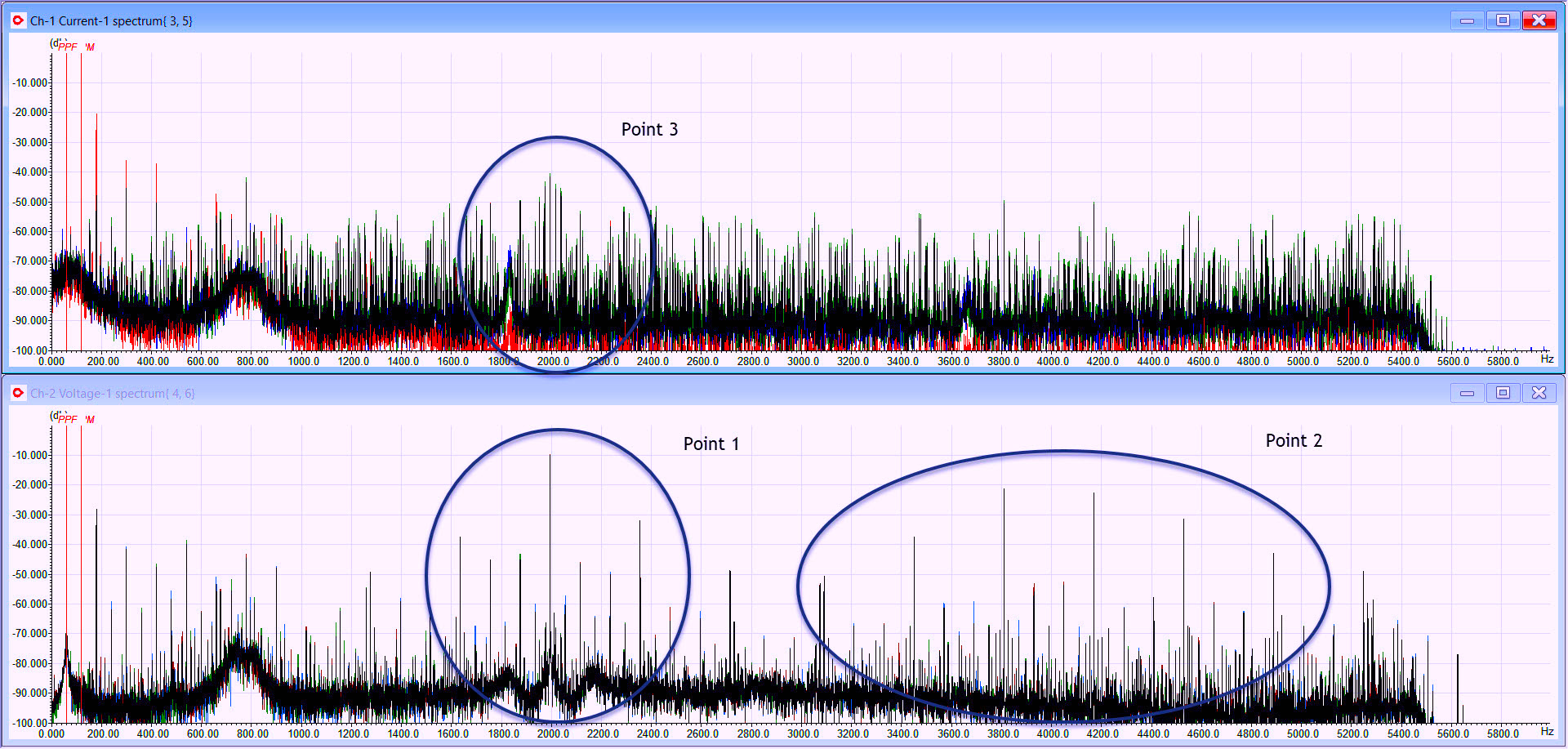
Fig. 3. Point 1 center peak is the inverter carrier (firing) frequency with sidebands.
Point 2 is the harmonic with sidebands. Point 3 is resonance with the transformer.
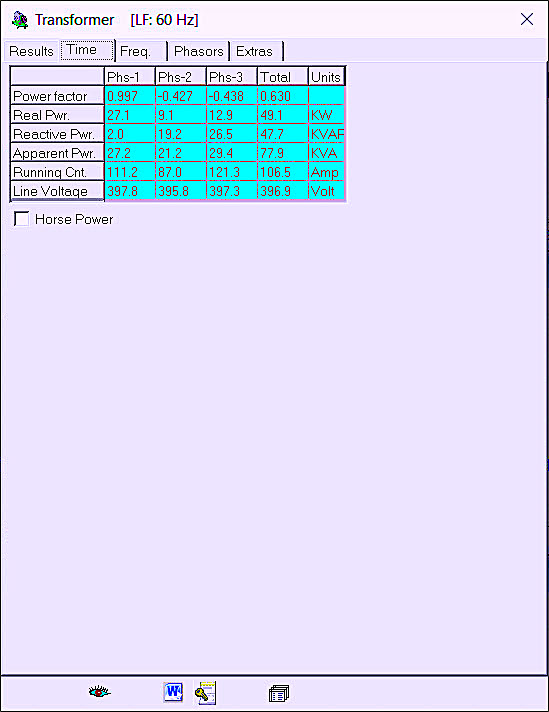
Fig. 4. Loading information on the first primary coil of the transformer.
In our next example, the transformer is lightly loaded on the half of the primary shown in Fig. 4. The second half of the primary carries much lower harmonics (Fig. 5). And, although the second half carries a heavier load (Fig. 6), the resonance in (Fig. 7, Point 3) versus that in the other primary surrounding 2khZ (Fig.3, Point 3) is much higher.
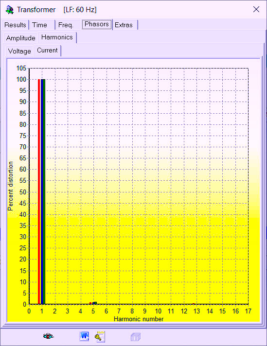
Fig. 5. Current THD of second winding of transformer primary.

Fig. 6. Data showing higher power in second primary winding.
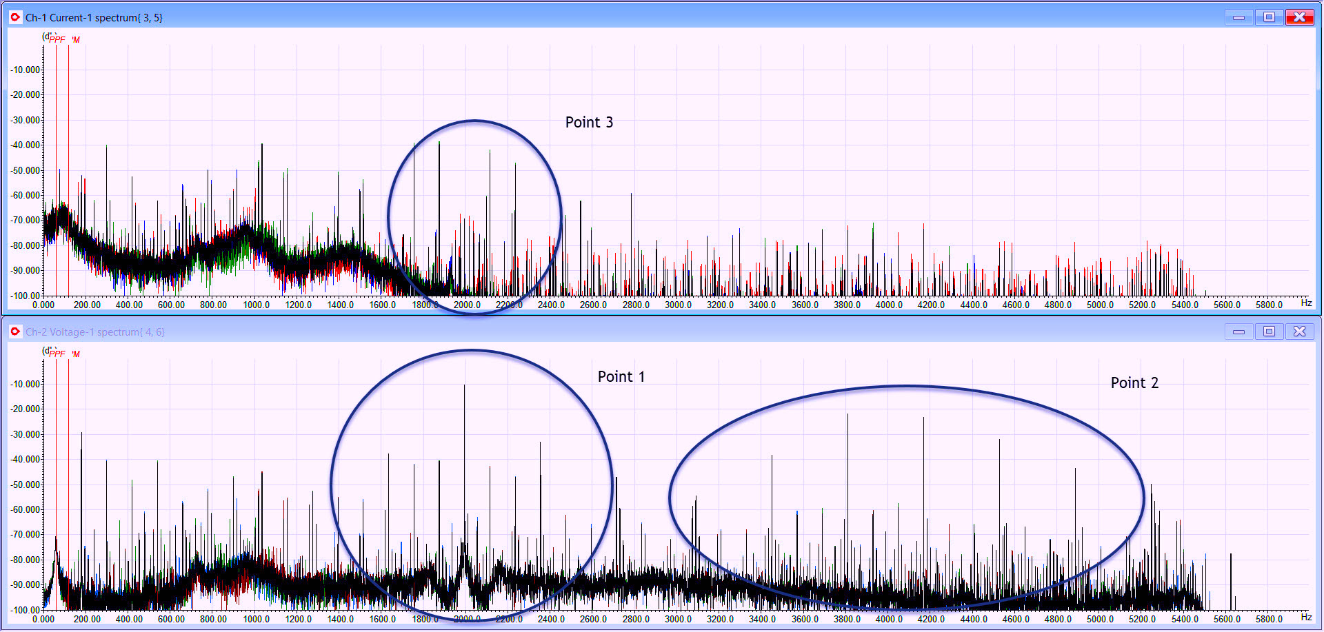
Fig. 7. Second primary winding showing inverter firing frequency with sidebands (Point 1),
harmonic with sidebands, and higher resonance in transformer (Point 3).
While this situation is not always found in utility-scale solar plants, unbalanced transformer primaries lead to phase-balance conditions, resonance, and heating, as well as potential balance issues in the secondary. The correction for such conditions is to balance the load on the primaries, which, in turn, can reduce transformer heating and intermittent trips.
Part IV of this series will discuss a fault in an open dry-type transformer, following a high transient that altered the shape of at least one coil.TRR
ABOUT THE AUTHOR
Howard Penrose, Ph.D., CMRP, is Founder and President of Motor Doc LLC, Lombard, IL and, among other things, a Past Chair of the Society for Reliability and Maintenance Professionals, Atlanta (smrp.org). Email him at howard@motordoc.com, or info@motordoc.com, and/or visit motordoc.com.
Tags: reliability, availability, maintenance, RAM, electrical systems, transformers, electric motors, generators, Electrical Signature Analysis, ESA, Motor Signature Current Analysis, MCSA, predictive maintenance, preventive maintenance

