As discussed in Parts I, II, and III about our ongoing literature searches and analyses of failure models associated with stator-winding defects, we have developed two theories surrounding the detection of faults in the stator. In one theory, the defect would be associated with the synchronous speed developed by the stator. In our second theory, the defect would be associated with the running speed of the rotor. Practical applications support the second theory, but an analysis of the problem is necessary to ensure the detection of the defect. We will follow our findings with an approach to vibration analysis and related signatures.
NUMBERS DON’T LIE
It’s important to first note that conditions associated with both the rotor and stator defects, from a magnetic standpoint, relate to a concept referred to as Unbalanced Magnetic Pull (UMP – see referenced reading at the end of the article). This is normally related to rotor eccentricity and the reason electro-mechanical defects can be detected with vibration. However, it’s also important to remember that the movement of stator components, such as a coil moving toward and away from the rotor, and missing components, such as magnetic wedges, result in a condition that’s similar to a rotor being eccentric. Rotor eccentricity is well established in literature with the following Electrical Current Signature Analysis (ESA) / Current Signature Analysis (CSA) formula (Equation 1 below).
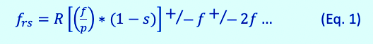
Where frs are the associated peaks for rotor static eccentricity, f is the line frequency, R is the number of rotor slots, p is the pole pairs (i.e., 4-pole = 2), and s is the operational slip for induction machines, slip is negative for asynchronous generators. The slip, in this case, can be thought to be associated with the rotor lagging behind the rotating magnetic field in the stator for an induction machine or leading in an asychronous generator (which is shown in Equation 2 below).
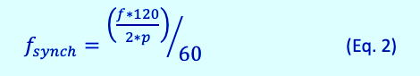
This would lead to the first theory concept that stator slot defects would relate to the rotating field at fsynch (synchronous frequency). For instance, a four-pole motor at 60 Hz would have a rotating frequency of 30 Hz. As the magnetic field rotates within the stator at synchronous speed the defect could occur at the synchronous speed times the number of stator slots. This means that the peaks would show at harmonics of the line frequency. If we apply this to a synchronous motor, in which the angle between the rotating field and the rotor field are stationary in relation the rotor, the rotor is turning at exactly the same speed as the rotating field, but lags by a mechanical angle.
However, where the concept falls apart for the induction motor is related to the air-gap magnetic field. In the case of the induction motor, the effect is as the magnetic field of the rotor passing the associated stator slot. For purposes of evaluating a stator, we can reverse them mathematically where the stator is rotating around the rotor. This works with the concept of static eccentricity and UMP, with the UMP primarily involving the radial movement of a loose coil or the effective magnetic balance relating to one or more missing magnetic wedges.
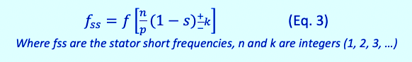
Slip is associated with the stator, as is evidenced with electric winding shorts, which is well documented in literature (as shown in Equation 3 below).
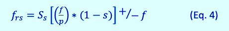
With rotor static eccentricity, as shown in Equation 1, the stator can be evaluated as the number of slots times the running speed, due to the relationship of stator slots and the resulting UMP. The value of UMP is expected to be much smaller than rotor eccentricity, which can be measured in millimeters, versus stator-coil movement, which may be measured in smaller increments. The stator-beat frequency remains consistent in both from a vibration and ESA standpoint. The result is found, as shown in Equation 4 below, for induction motors, but with fewer harmonics such that there would be only one line-frequency sideband. In this case, Ss is the number of stator slots.
In vibration analysis, the UMP is read as a result of the impact on the rotor resulting in sidebands that are different than a measurement through the magnetic field. The result from the impact on the rotor would be sidebands related to running speed instead of the line frequency.
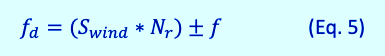
In both cases, the formula works out to Equation 5 (below), where Swind is the number of rotor bars or stator slots, Nr is the running speed, and fd are the defect frequencies for induction motors and asyncronous generators:
The purpose of magnetic wedges is to reduce air-gap flux-density ripple, as noted in the simulation performed in Part III of article series, and shown here as Fig. 1.
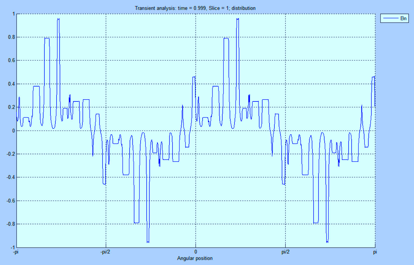
Fig. 1. Low-resolution air-gap flux-density ripples (Bn in Tesla), with all wedges in place.
The purpose of the magnetic wedges is to reduce vibration, heating and noise associated with torque ripple resulting from the air-gap flux density ripples as the rotor field interacts through the air gap. The use of the magnetic wedges reduces the amplitude of the ripples. The loss of one or more wedges increases the value, as shown in Fig. 2.
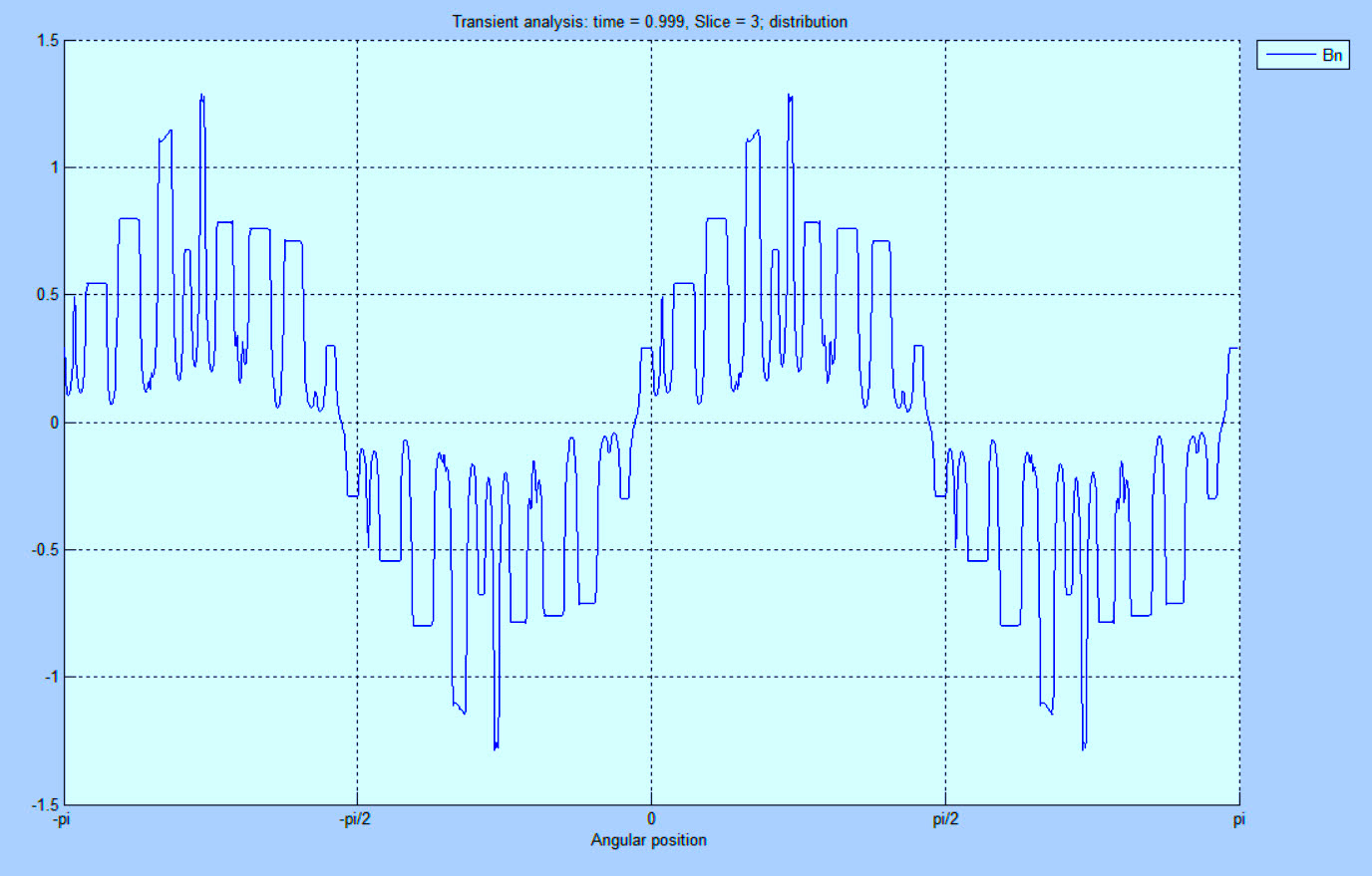
Fig. 2. Low-resolution air-gap flux-density ripples (Bn in Tesla) with a missing wedge.
The resulting missing wedge causes an increase in the associated stator beat frequency as the stator and rotor magnetic fields pass the fault point. The fault issue is compounded by the movement of the rotor as it passes over each affected stator slot as the variation of the air-gap field causes the rotor to move in a mixed eccentricity, which is calculated as noted in the referenced UMP paper at the end of the article.
It is noted that the movement of coils in a stator lead to similar effects, and will often result in a combination of missing magnetic wedges and coil movement. The results are similar with loose coils as the coil moves toward the rotor radially, increasing its effect on the rotor in the air gap and affecting the air-gap flux-density ripple. This may also result in conditions such as sparking or winding stresses in the machine as the combination of missing wedges and coil movement advance in larger machines, or just coils moving significantly in smaller machines.
The following example (shown in Figs. 3 and 4) involves a 2MW, 4-Pole, 600 Vac wind-turbine asynchronous generator with 60 rotor bars and 72 stator slots, operating at 1803.3 rpm (30.056 Hz). When applying Equation 5, the frequencies for the stator slots are 2104.03 Hz and 2224.03 Hz. The stator-slot frequencies should not exist in a good winding with results shown in Fig. 3. Often an amplitude of at least 5 dB above the noise floor is a good point for action.
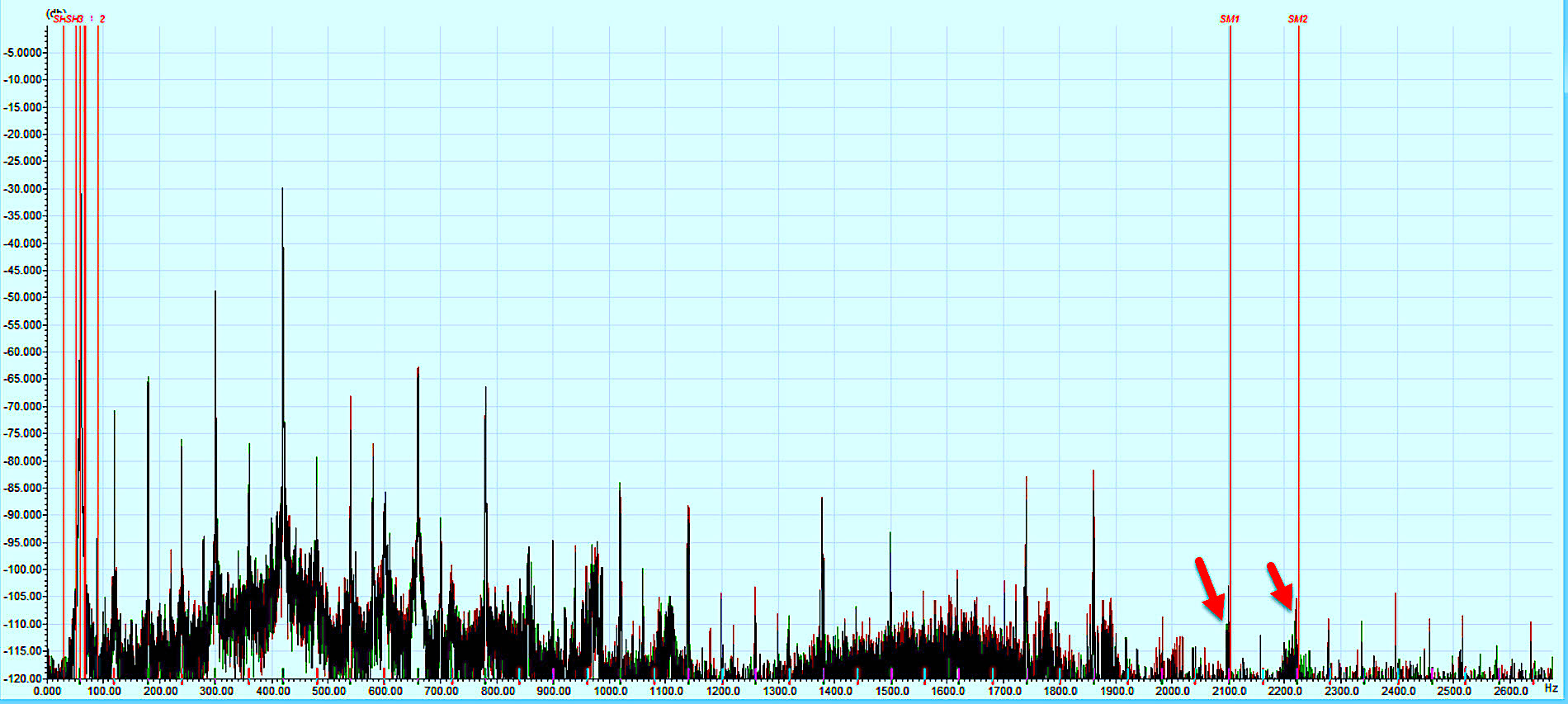
Fig. 3. Stator-slot defects with amplitudes of approximately 10dB above the noise floor.
Stator winding stress frequencies for this stator would be mirrored on either side of line frequency as line frequency +/- Equation 3, with n = 1, 2, 3 resulting in 29.972 Hz, 90.028 Hz, 120.056 Hz, and 150.084 Hz (as shown in Fig. 4).
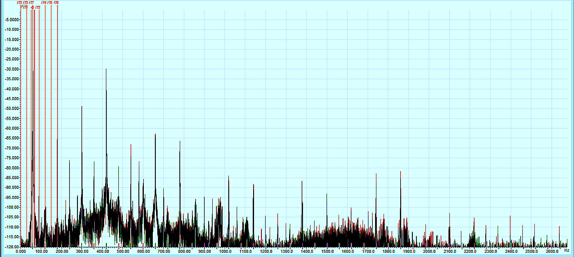
Fig. 4. Stator-winding stress with amplitudes greater than 5 dB above the noise floor.
The combination of the stator-slot defect and winding stress indicate that magnetic wedges are missing and that the coils are moving, resulting in slot sparking or other excessive leakage between the coils and ground. Alternately, there are missing wedges and winding defects in the stator. In either case, action will be required.
BOTTOM LINE AND MORE
Our research has found that stator-slot frequency is related to the number of stator slots times the running speed of the machine for both induction motors and asynchronous generators, even when operating above synchronous speed. In Part V of this series, we will focus on how this finding is applied, what to expect for alarm levels, and, as a special treat for our vibration-focused friends, provide a discussion of how these data sets appear in vibration data.TRR
UMP REFERENCE
“Rotordynamic Simulation Method of Induction Motors Including the Effects of Unbalanced Magnetic Pull,” Kim, Nerg, Choudhury, and Sopanen, IEEExplore Opensource, January 23, 2020, Finland.
Click On The Following Links To Read The First Three Articles In This Series:
“Part I, Electrical Signature Analysis (ESA) & Stator Winding Issues” (Oct. 3, 2020)
“Part II, Electrical Signature Analysis (ESA) & Stator Winding Issues” (Oct. 9, 2020)
“Part III, Electrical Signature Analysis (ESA) & Stator Winding Issues” (Oct. 17, 2020)
ABOUT THE AUTHOR
Howard Penrose, Ph.D., CMRP, is Founder and President of Motor Doc LLC, Lombard, IL and, among other things, a Past Chair of the Society for Reliability and Maintenance Professionals, Atlanta (smrp.org). Email him at howard@motordoc.com, or info@motordoc.com, and/or visit motordoc.com.
Tags: motors, drives, generators, wind turbines, wind energy, motor testing, reliability, availability, maintenance, RAM, electrical signature analysis, ESA, current signature analysis, CSA, motor current signature analysis, MCSA, vibration analysis

