Following publication of Parts I and II of this series (Oct. 3, 2020, and Oct. 9, 2020, respectively), we continued our literature search for information on stator analysis (from academic and other types of technical papers). And, unfortunately, we continued to come up with limited results. Here, in Part III, we discuss a few of our own thoughts and theories related to where the stator frequencies for loose coils and missing wedges would reside.
As part of our investigation, we performed Finite Element Analysis (FEA) using FEM (Finite Element Method) models to support the type of data we observed in the field using MatLab and MotorAnalysis software. To randomize the analysis, we utilized a standard machine example in MotorAnalysis, as shown in Figs. 1 and 2.
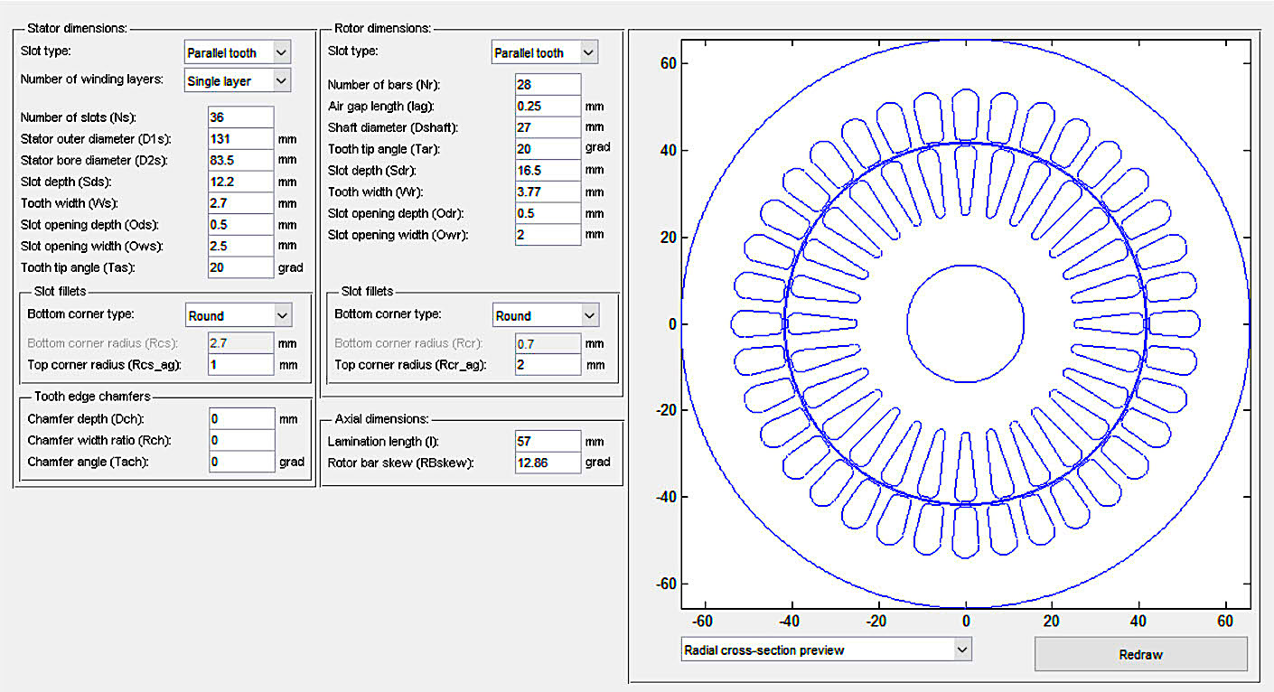
Fig. 1. Mechanical and electrical setup for FEA/FEM analysis of a 4-pole electric motor.
This motor model fully analyzes both the stator windings and rotor construction including materials. The challenge is that it would allow rotor defect analysis, but not stator defect analysis, requiring us to create functions to represent the changes that we needed to review for a generic slot defect. As part of the model, we selected one slot and generated the defect, which was warned as an unbalanced variation of the design.
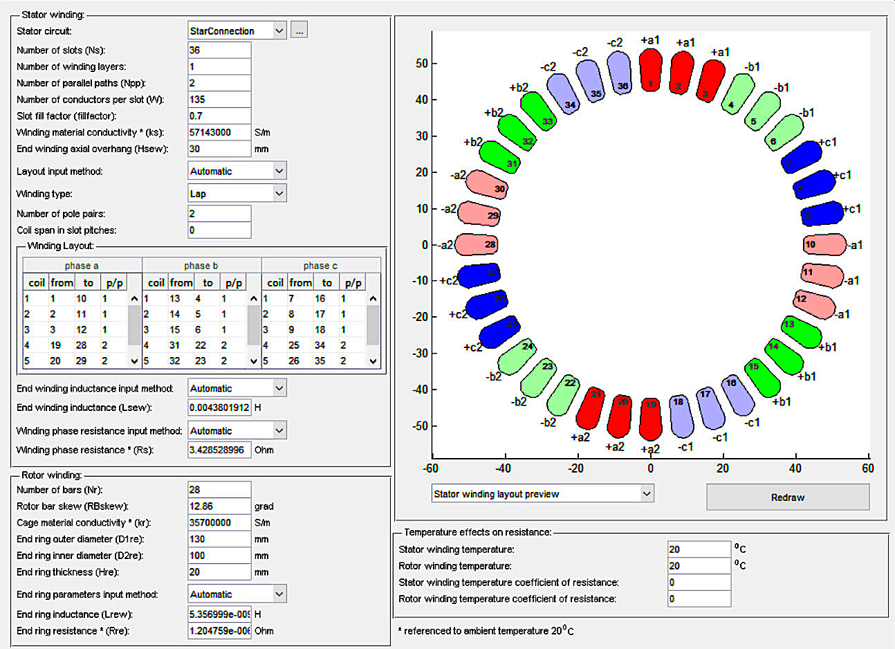
Fig. 2. Winding design and connection of the stator including specifics for modeling.
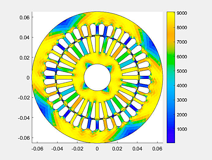
Fig. 3. Magnetic map of 2-dimensional stator design.
Figure 3 is the resulting magnetic 2D map of the stator design for the analysis of the theories of interest and to determine how different FEA/FEM models handle magnetic fields and the interactions between the stator and rotor. It’s important to note that electric-motor specific software, such as SPEED, was not used as part of the study. Instead, we used a custom MatLab model.
The application of the FEA analysis showed as Figs. 4 and 5 below.
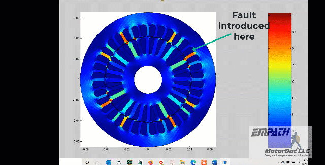
Fig. 4. Magnetic field and strength map in rotation with introduced fault.
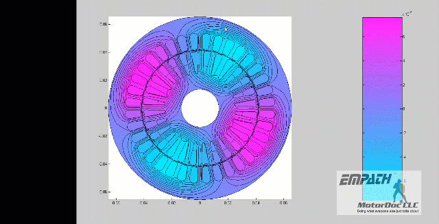
Fig. 5. Magnetic lines of flux mapped in rotation without fault.
When the air gap is analyzed in these models, the fields vary between the stator with a defect and the one without a defect, as shown in Figs. 6 and 7.
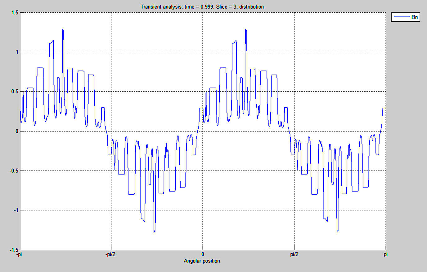
Fig. 6. Stator with defect at 0.999 seconds Bn (Magnetic Field – in Tesla(T) units).
AUTHOR’S NOTE: in Figs. 6 and 7, the peaks (up then down) represent the magnetic field interacting with each slot in the airgap. In this case, although the resolution is poor due to 0.001 increments versus 0.00005 increments (10-5) which is what would normally be used, the total peaks up and down equal 36. The lower resolution was used for time as the simulation would take 72 hours to complete at high resolution versus four hours with the lower resolution. The points are instantaneous with the rotor at one point, as opposed to rotating. The high peaks that appear in Fig. 6 relate to the defect and its impact on all four poles.
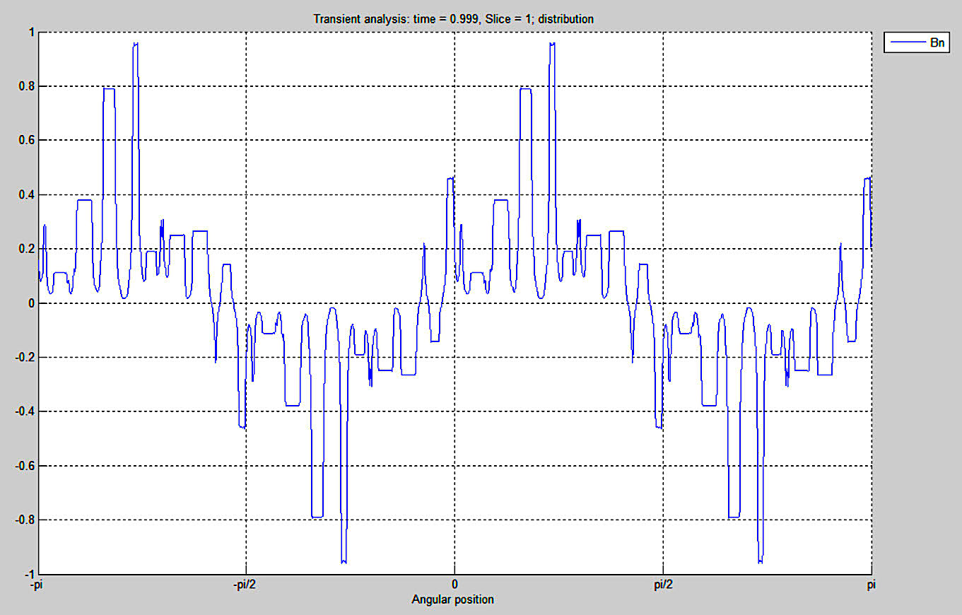
Fig. 7. Stator without defect Bn mapped at 0.999 seconds.
The defect had additional peaks to ~1.3T and the good model had fewer peaks to ~0.98T. This indicates that the models identified the impact of the defect. However, one part of the analysis that’s not as effective is the visual portion of the model, in which the magnetic fields (Reference Figs. 4 and 5) in the stator and rotor directly across from each other are incorrect. The fields are shifted in a rotating field such that the rotor lines should be lagging behind the stator lines, but also rotating at synchronous speed, which is Nsynch = (120*frequency)/number of poles. The mechanical portion of the rotor lags behind the synchronous speed by a slip value (Nslip) resulting in the shaft speed of Nsynch – Nslip = Nrot.
All of the theories associated with induction-motor-stator-defect analysis use Nslip as part of their calculations. The rotor defects are all associated, and well documented, as the running speed times the rotor slots with line frequency sidebands for current and electrical signature analysis. The paper discussed in Part II of this series was close, and the formula worked for a specific operating speed, for stator frequencies. Based upon how the fields interact between the stator and rotor, there are two approaches to the analysis from a theoretical standpoint.
FIRST THEORY: The magnetic field wave, which is the magnetic synchronous speed in the stator, will interact with the defect resulting in Nsynch * SS (stator slots) +/- fl. If the magnetic fields operated the same as shown in Figures 4 and 5, then these would be accurate and we would see these in a power harmonic spectra.
SECOND THEORY: Based on the shift in magnetic field (lag) between the stator and rotor and the interaction of the fields, the result would actually be: [SS * ((1-Nslip)*(fl/p)] +/- fl where, SS are the stator slot number, Nslip is the percent slip, fl is the line frequency, and p is the pole pairs. This would include slip and result in what we believe the paper in Part II meant, such that a motor with 36 slots, a slip of 0.03 (3%), line frequency of 60 Hz, and 4 poles (2 pole pairs) would be [36*((1-0.03)*(60Hz/2)] +/- 60Hz = 1,047.6 +/-60Hz. This would result in the same as (36 (SS) * 29.1Hz (RPM)) +/- 60Hz.
COMING UP
Despite having noted previously that this series on ESA and stator winding issues would be limited to three parts, we now realize such a plan won’t work, given the scope of the topic and findings of our research and observations. Thus, stay tuned for Part IV, where we will put both of the above theories to the test.TRR
Click On The Following Links To Read The First Two Articles In This Series:
“Part I, Electrical Signature Analysis (ESA) & Stator Winding Issues” (Oct. 3, 2020)
“Part II, Electrical Signature Analysis (ESA) & Stator Winding Issues” (Oct. 9, 2020)
ABOUT THE AUTHOR
Howard Penrose, Ph.D., CMRP, is Founder and President of Motor Doc LLC, Lombard, IL and, among other things, a Past Chair of the Society for Reliability and Maintenance Professionals, Atlanta (smrp.org). Email him at howard@motordoc.com, or info@motordoc.com, and/or visit motordoc.com.
Tags: motors, drives, generators, wind turbines, wind energy, motor testing, reliability, availability, maintenance, RAM, electrical signature analysis, ESA, motor current signature analysis, MCSA, vibration analysis

