Last week’s article (March, 13, 2021), “Evaluation Of Medium And High Voltage Machines with Motor Circuit Analysis (MCA)” sparked quite a bit of interest. That included substantial on- and off-line discussion about low- and high-voltage testing. Based on articles and debates over the past three decades, some assumed that the article was promoting one technology over another. In reality, the article was more about selecting off-line tests for in-place motors that would provide real results without potentially causing damage. One of the topics that came up was the use of 2E+1,000 Volt surge-comparison tests on used windings, which is frowned upon in most standards.
A major question that arose from the various discussions was about rushing to test either with high-voltage MCA, i.e., surge-comparison and high-potential testing, or low-voltage MCA, i.e., capacitance, impedance, insulation-resistance profiles, and other tests, without information on condition. For instance, the article noted that the low-voltage test was selected for a synchronous motor rotor that was wet and oily per visual and insulation-resistance profile inspections. In the other example described in the article, a visual inspection and off-line partial-discharge test identified that contamination was having an effect on the insulation system.
The real discussion concerned the situational awareness, or context, of the operations, condition of the machines, owner’s definition of failure, and other areas that would influence decisions related to the equipment and recommendations. What’s often forgotten is the needed visual inspection, understanding of the machine, and understanding of how the test equipment operates and provides an answer.
For example, in the case of the 4,500-hp synchronous motor, the rotor incorporated edge-wound windings that had little insulation between the edge of the coil and the pole piece for each of four poles in the machine. Contamination between a pole piece and exposed edges of the coil would arc and carbon-track if exposed to high voltages. Therefore, the low-voltage testing approach made more sense, particularly when coupled with an insulation resistance profile to determine the condition of the windings and possible presence of a contamination bridge (there was). A mistake, in this case, would have resulted in hundreds of thousands of dollars in repair costs and the related outage.
MY STANDARD APPROACH WHEN EVALUATING MOTORS
Whenever I approach a machine before testing, I do the following:
1. Discuss with the machine owner(s) what the impact of the machine is; at which point they
determine the machine has failed; and what risk(s) they willing to take should faults be found.
2. Identify the operating context of the machine, including the ambient environment.
3. Perform a visual inspection of the machine, including removing accessible covers.
4. Determine if the owner has any specific testing requirements.
That last bulleted item can be troubling, as I’ve been in situations where an owner’s “required” testing is well beyond what should be applied to a specific machine. It’s also important to understand that a visual inspection trumps all testing. For example, if the winding is dry and brittle, it doesn’t matter what the test results are. The unit has failed.
If the owner of the equipment is risk-adverse, then the decision to take action comes much sooner, as visual and test indicators dictate. In once instance, a large manufacturer had a specification that any sign of bearing degradation in vibration would cause a motor to be pulled from service. The result was hundreds, if not thousands, of hours of increasing-risk use were avoided and new components installed, or motors replaced. In another case, though, a bearing fault was detected in a motor and an assessment of 20% chance of surviving 600 hours to the next shutdown was produced, and the motor was allowed to run. Interestingly, during a later evaluation of the bearing, the cage was found to have basically disintegrated, but the motor still operated, although at a much lower efficiency.
Then we come to the insulation tests and one of the points of the entire exercise (in last week’s article): What voltage would be applied if a high-potential test and surge comparison test were performed on a used winding? Also, what decisions are made as you progress through testing to determine if you stop or continue moving forward?
In high-voltage MCA, such as using the Electrom iTIG II, the Baker D12, or the Baker AWA, a progression of tests are performed. These include:
1. Phase-to-Phase Resistance test: determines the continuity of the circuit and if
there are broken parallel conductors.
2. Insulation Resistance test: determines if the motor is grounded, or falls below
a value recommended before high stress tests.
3. Dielectric Absorption or Polarization Index test: determines conditons of
winding or if they are contaminated.
4. High-Potential test (DC): measures leakage and determines if the winding
is at risk for operating and high voltage testing.
5. Surge Test/PD Surge: detects winding defects such as shorts or weakened
insulation systems.
The iTIG II (and later versions) and Baker D-series, have low-voltage testing options, as shown in last week’s article. I like to use those as part of the testing series, so that any circuit defects are detected in advance of the high-potential and surge testing. In cases where there are obvious defects, such as contamination, I normally go the low-voltage MCA route. Where conditions are unknown and I want a confidence-raising answer in a hurry, I will also go with low-voltage MCA.
If I am applying a maintenance high-potential and surge-comparison test on a winding, what values do I use? The common “rule of thumb” that’s been kicked around for many years is the new-winding application of 2E+1000 for the surge test and (2E+1000)*1.7 for the high-potential test. However, insulation systems begin aging right from the start, as well as through exposure to the operating environment. Standard developers take this into account when they make maintenance testing recommendations. In fact, 2E+1000 Volt is no longer found in the IEEE standards for surge testing, and the new winding values vary significantly.
In the case of the DC high-potential test, there is a specific Institute of Electrical and Electronics Engineers, Inc. (IEEE) standard 95, “IEEE Recommended Practice for Insulation Testing of AC Electric Machinery (2300 V and Above) with High Direct Voltage.” For all practical purposes, this is the same standard referenced for low-voltage (480V and up) electric motors by most technicians and owners. According to section 6.2, “Test Voltage for Maintenance Proof Testing,” the value would be 125 % to 150% of the line-to-line voltage (for AC high pot) times 1.7 for DC high-potential testing. That would mean that a 4,160V machine would be DC-high-potential tested at 10,600 Volts DC. It is noted that the section also states: “The test voltage for maintenance proof testing under special conditions of insulation age, damage, or in light of other considerations may require variation from the range indicated.” In effect, the applied voltage is called out at a lesser value.
The surge-comparison test, on the other hand, is a slightly more interesting discussion. How the test is performed depends on the number of impulses per second that the instrument performs; the rise time of the impulses; and the method producing the impulse. Then it depends on which standard you pick up.
The most commonly referenced standard is IEEE 522, “IEEE Guide for Testing Turn Insulation of Form-Wound Stator Coils for Alternating-Current Electric Machines,” in which Section 7, “Maintenance Tests or Tests After Installation of Machines,” is used for equipment in the field. First, the impulse rise-time must be determined, and is called out by the standard as 0.1-0.2 usec, as the 1.2 usec will stress the ground insulation. The value called out for a new insulation in section 6.2, “Standard (3.5 p.u.) Withstand Envelope,” is shown here in Equation 1:
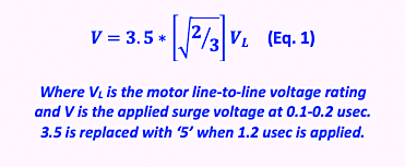
Section 7 calls for a multiplier of 0.75 to V for maintenance tests. That would mean a 4,160V motor should see no more than 8,920 Volts, which is slightly less than 2E+1000. However, there are a number of considerations outlined in the standard and even a reference to 75% of 2E+1000, which would be 6,990 Volts.
On the other hand, IEEE 1068, “IEEE Standard for the Repair and Rewinding of AC Electric Motors in the Petroleum, Chemical, and Process Industries,” section 5.2j states, “The surge comparison test, if performed prior to cleaning of the winding, should be done at the motor’s rated voltage.” This would mean that the surge test on the same motor should not exceed 4,160 Volts when the winding has contamination and moisture present. Even after cleaning and drying the stator, Section 6.1 calls for: 1.21 times the nameplate voltage when using a 0.1 usec rise time; 1.4 times for 0.5 usec; and, 1.72 times for 1.2 usec. This would mean that an applied voltage for the 4,160 Vac motor would range from 5,035 Volts to 7,155 Volts.
IEEE 1415, “IEEE Guide to Induction Machinery Maintenance Testing and Failure Analysis,” in Section 4.3.28, “Surge Test,” simply references IEEE 522 “or OEM.” In essence, the applied maintenance surge test can range from 5,035 Volts to 9,320 Volts, depending on the conditions and the reference. This means that understanding the operating context is even more important.
CAUTIONS REGARDING POTENTIAL DESTRUCTION
In all cases, high-voltage MCA tests require great caution when applied to used windings. NFPA 70B, “Recommended Practice for Electrical Equipment Maintenance,” refers to the test voltages for AC and DC high-potential tests, but specifically does not provide a test value for surge testing. What we do know is mentioned in IEEE 522: that at least 350 Volts potential must be present across the winding defect to be detected. Due to decay in the system, the value tends to be reflective of the expected impulses when a breaker closes and bounces, causing voltage impulses to the first few turns of the motor winding.
The question that arises from all of this is: “Which voltage do I use for my high-voltage MCA testing?” The answer is simple: “It depends.” The NFPA 70B states, under 11.20.4.4, “The testing and interpretation of results should be conducted by a trained professional.” Unfortunately, as noted above, there is limited guidance to the professional. It is equally important to note that there are no standards that cover surge testing of random-wound (low-voltage) electric motors.
As a motor shop professional, I would turn to the Electrical Apparatus Service Association (EASA) Technical Manual, under surge-comparison testing. In Section 7, it simply references the IEEE 522.
In the end, the issues raised in the referenced March 13, 2021, article and discussed here relate to how risk averse a motor owner and technician are when it comes to performing high-voltage MCA. The first thing is to determine if the insulation system is in distress through aging or contamination. If it is, reconsider surge testing and conduct a visual inspection or low-votlage MCA testing. If the insulation system appears to be in good shape, perform the following:
1. Phase-to-Phase Resistance test: values should be 3-5% maximum (ref. IEEE 1415).
2. Other low-voltage tests that I recommend are:
-
-
-
- Impedance – less than 3% corrected for rotor position
- Inductance – there is no standard, but recommend less than 3%
when corrected for rotor position - Capacitance – trended value
- Phase Angle – +/-1 with a rotor
- I/F – +/-1 with a rotor
- Other tests should also be balanced.
-
-
3. Insulation Resistance test as prescribed in IEEE 43: 5 Megohms for random wound and
100 MegOhms for form wound after temperature correction. These are NOT pass/fail values
for the winding, just recommendations before applying high voltage tests.
4. Dielectric Absorption or Polarization Index test: recommend values are greater than 2 when looking
at the ratio of final test divided by initial test. If the insulation system is over 5000 MegOhms, the
value should not fall under 1.0.
5. High-Potential test (DC): [(2E+1000)*.65]*1.7. Follow a “step test” method, which will allow
trending of leakage values. If the tests deviate from a straight or slightly curved line before the
high value is reached then the test fails (do not surge at this point).
6. Surge-Comparison test: Reference Equation 1 multiplied by 0.75. Using one of the testers that
are mentioned above, the tester should stop any test should a fault occur.
-
-
-
- 460 Volts = 985 Volts
- 2300 Volts = 4925 Volts
- 4160 Volts = 8910 Volts
- 12,400 Volts = 26,560 Volts
- 13,800 Volts = 29,560 Volts
-
-
Tests should be adjusted down from these values depending on conditions. The end result of the above covers the strengths and weaknesses of the other tests and represents a progression of testing toward, as defined in IEEE 1415, potentially destructive tests.
Remember: The objective is to identify defects before equipment fails and leave the ability to operate the equipment while planning for a spare, repair, or replacement.TRR
ABOUT THE AUTHOR
Howard Penrose, Ph.D., CMRP, is Founder and President of Motor Doc LLC, Lombard, IL and, among other things, a Past Chair of the Society for Reliability and Maintenance Professionals, Atlanta (smrp.org). Email him at howard@motordoc.com, or info@motordoc.com, and/or visit motordoc.com.
Tags: reliability, availability, maintenance, RAM, electric motors, drives, motor testing, Motor Circuit Analysis, MCA

