Low- and high-voltage Motor Circuit Analysis (MCA) methods have existed since the 1950s, with low-voltage MCA technology becoming commercially viable in the 1980s. Since the mid-1980s, MCA technologies have become more prevalent as part of predictive-maintenance (PdM) and motor diagnostics programs across all industries. While the descriptions of these technologies are “low” and “high” voltage, they describe the types of outputs from the instruments, not the types of electric machines tested. This article explains the concurrent application of low- and high-voltage MCA on 4,160-volt induction machines and 13.8 kV synchronous motors.
The technologies studied include:
- Amprobe 5 kV Insulation Resistance Tester (AMB55) for insulation resistance, polarization index, dielectric absorption, dielectric discharge, rotor test, and capacitance to ground.
- ALL-TEST PRO 5 (ATP5) for resistance, inductance, impedance, phase angle, current/frequency response, insulation resistance, capacitance to ground, and dissipation factor. Other than resistance and insulation to ground testing, the circuit tests are frequency based.
- Electrom iTIG II D12 (iTIG) for resistance, inductance, impedance, phase angle, capacitance, Q-factor, rotor influence test, insulation resistance, polarization index, dielectric absorption, high-potential test, surge comparison testing, and PD surge.
The goal of the study was to determine how the test results and findings compared among technologies, and their accuracy. Each of the technologies studied is designed for field application, as well as in the original equipment manufacturer (OEM) and service industries. The low-voltage MCA devices are relatively lightweight across all voltages, while the high-voltage instruments increase in size and weight as the voltage and machines being tested increase.
The types of motors tested in this study were form-wound induction and synchronous machines. They were open, drip proof (ODP), WPII, and TEWAC units that varied in size from 300 to 4500 horsepower, and 900 to 1,800 rpm. Each machine had power factor correction capacitors that need to be disconnected for either low or high voltage testing. While testing can be performed at these leads, since the tests would evaluate the cables and motors in parallel, the motor leads were disconnected in order to evaluate the motor insulation system only.
4,160 VOLT INDUCTION MOTOR
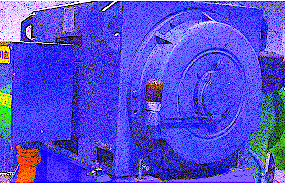
The first machine evaluated was an ODP 300 hp, 885 rpm, 4160 Vac, form-wound electric motor (similar to Fig. 1) that had some visual level of contamination. While no specific test results indicated the contamination was an issue, the unbalanced partial discharge (PD) levels may be an early indicator of insulation degradation.
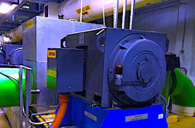
Fig. 1. A 300 hp, 885 rpm, 4,160 Vac induction motor.
The low-voltage MCA results in Table I show a balanced winding, with good insulation resistance results.
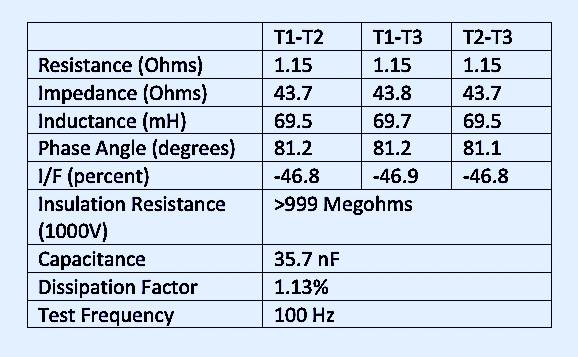
Table I. Low-voltage MCA Test Results (ATP5)
Table II and Fig. 2 are the low-voltage and high-voltage MCA tests. The data was balanced with the exception of PD, which was measured in picocoulombs and unbalanced. Off-line PD tests involve trending and/or comparison of phases or like motors to determine if there are changes or unbalances. In this case, the average PD from other machines was under 20,000 pC and relatively balanced. Thus, it was determined that a polarization index and insulation resistance profile (IRP) reading should be performed with the AMB55.
The motor also passed a surge test, indicating that any issues were early in nature and should be trended. Or, as an alternative, the motor needed to be removed, cleaned and put through a short cycle vacuum pressure impregnation (VPI) to fill in any cracks or surface voids.
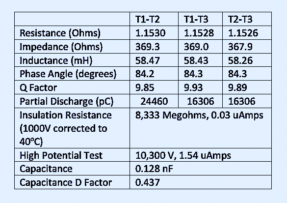
Table II. High and Low-votage MCA Tests (iTIG).
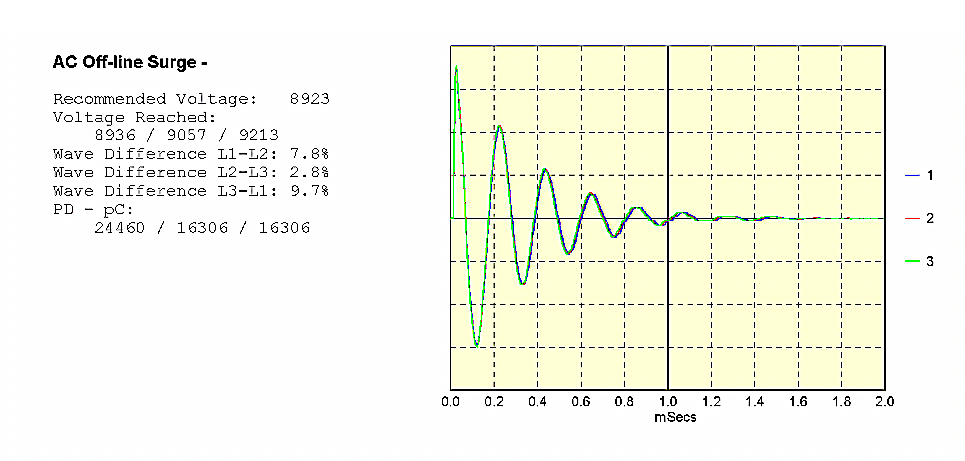 Fig. 2. Surge-comparison test and PD test of the 300 hp motor (iTIG).
The IRP was performed at 2500 Vdc and resulted in only a few small capacitive discharges, as shown in Fig. 3. The final conclusion was to plan an overhaul within the next three to six months.
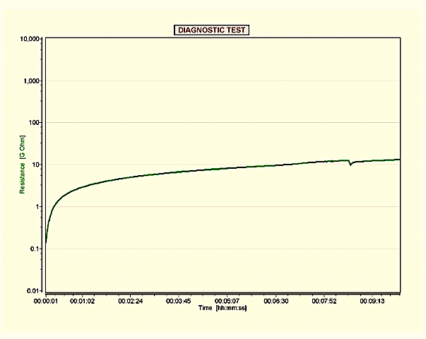 Fig. 3. IRP with small discharges starting at about seven minutes, indicating an aging insulation system (AMB55).
13,800 VOLT SYNCHRONOUS MOTOR
The 4,500 hp, 1,800 rpm, 13.8 kV synchronous motors evaluated in this study were similar to the unit shown in Fig. 4. It was determined that the rotors would be evaluated with an insulation-resistance test prior to performing any other testing. Since the values appeared to be relatively low, the team decided to use low-voltage MCA and IRP to evaluate the rotors (see Fig. 5 for findings from one of these rotors).

Fig. 4. A 4,500 hp, 1,800 rpm, 13.8 kV synchronous motor.
Since there were surge arresters in the machine-connection boxes, they were disconnected. Additionally, the rotor leads were disconnected for testing both the stator and the rotor to reduce the influence the rotor had on the stator and to protect the rotor electronics. When possible, both the low and high voltage MCA devices are able to adjust for rotor position. In the case of these machines, such an effort was not time effective.
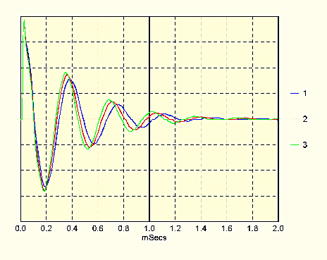 Fig. 5. Surge test results showed unbalance due to rotor position (iTIG).
The condition of the stator was known to have moisture and oil contamination and there was corona and partial discharge problems with the windings. The PD unbalance, shown in Table 3, would be expected from these conditions.
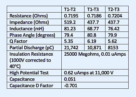 Table III. High- and Low-voltage MCA Tests of Stator (iTIG).
The stator had been tested four months prior to using low voltage MCA, allowing for a comparison between the previous and present data. Table IV represents the data taken the first time and Table 5 is the second set of data used to determine how quickly there is degradation of the insulation system in order to make reliable time to failure estimations.
Previous data identified some issues with the condition of the rotor insulation. While there are conditions with the stator, in this case, the rotor is the weakest part of the chain. Additional work was performed to evaluate the condition of the rotor insulation.
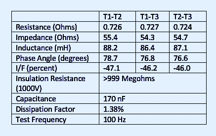
Table IV. Low-voltage MCA Test Results on Stator, 4 Months Prior (ATP5).
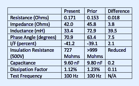
Table V. Low-voltage MCA Test Results on Rotor Comparison, Present and 4 Months Prior (ATP5).
The changes, particularly where inductance and impedance are concerned, identify the potential for a winding short in the rotor. Additional testing would be necessary to confirm the condition of the rotor.
The increase in discharges seen in Figs. 6, 7, and 8 indicates the synchronous-motor rotor was rapidly decaying. The reasons for degradation were found following the second round of testing, with those findings outside the scope of this article.
The challenge, in this case, was that the high-voltage MCA device could potentially “finish off” the rotor, thus removing the decision to continue operating the machine from the user. In this case, the use of low-voltage MCA and IRP was extremely valuable because the problem was found, and the user had the option of continuing usage without the potential of finishing off the insulation system.
 Fig. 6. IRP of rotor at 500 Vdc indicating aged insulation system (AMB55).
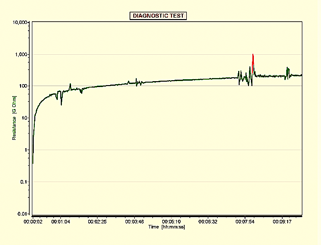 Fig. 7. Rotor analysis 4 months after the motor had been idle for several weeks (AMB55).
 Fig. 8. Rotor after attempting to start the machine (AMB55).
IN CONCLUSION
The use of low- and high-voltage MCA testing provided similar results. One of the primary differences was found with the synchronous motor rotor, where high-voltage tests may have finished off the insulation system.
Another concern was the need for a “booster” (Fig. 9) to meet the surge and high-potential voltages necessary for the 13.8 kV system.
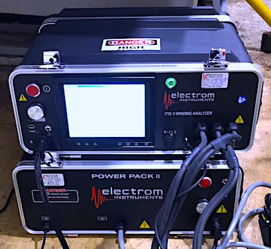
Fig. 9. iTIG unit with booster pack for up to 40 kV for surge and high-potential-voltage testing situations.
The use of 11,000 volts versus the 18,500 volts that should have been used was based on previous predictive maintenance tests. In both cases, the high-voltage MCA device required access to an outlet with a reasonable output voltage. The instrument used for this study has a built-in power conditioner that reduces the impact of power-quality issues on the test results.TRR
ABOUT THE AUTHOR
Howard Penrose, Ph.D., CMRP, is Founder and President of Motor Doc LLC, Lombard, IL and, among other things, a Past Chair of the Society for Reliability and Maintenance Professionals, Atlanta (smrp.org). Email him at howard@motordoc.com, or info@motordoc.com, and/or visit motordoc.com.
Tags: reliability, availability, maintenance, RAM, motors, drives, motor testing, Motor Circuit Analysis, MCA, motor rotors, motor stators, induction motors, synchronous motors, variable frequency drives, VFDs

