Power harmonics are power-frequency notches in sinusoidal Voltage or Current that occur due to switching power supplies. In single-phase supplies, such as laptops, lighting, displays, and similar, you have 3rd harmonics. That means, if you have a 60Hz system, the 3rd harmonic would be 3*60Hz = 180Hz.
Multiples of 3rd harmonics would be the odd harmonics associated with these multiples, so that you would have 3rd, 9th, 15th …. Together, these become additive currents in the neutral or grounding system and, in turn, play a role in problem situations. For example, increased numbers of computers and single-phase power supplies in older facilities often lead to overheating or electrical fires associated with undersized neutrals.
In the case of 3-phase systems, you would have the number of power electronics +/-1 as the base harmonics such that a standard 3-phase supply would have six power-electronic modulesresulting in the 5th and 7th harmonic. This would be in applications such as standard variable frequency drives and would have odd multiples of the 5th and 7th harmonics (11th and 13th, 17th and 19th, …). The impact of these harmonics is determined by how they would affect an electric motor where 5th harmonics are counter-rotating (backward) and the 7th harmonic would be pro-rotating (forward). The combination of high 5th and 7th and related harmonics result in even harmonics, i.e.,stationary heating harmonics, in the rotating components.
Even harmonics do exist. While not often referred to, they are the result of either odd harmonics or grounding systems. Even harmonics simply produce heating effects.
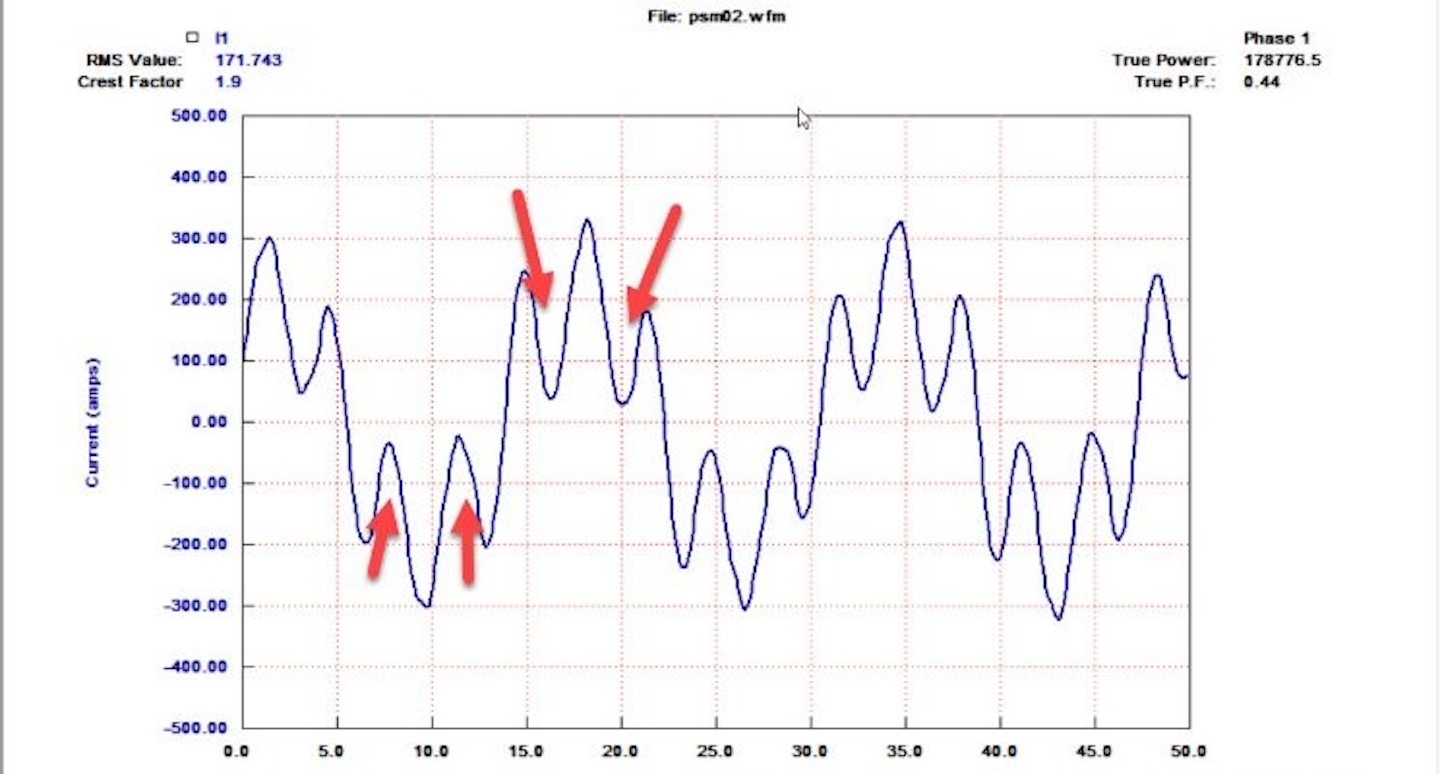
Fig. 1. 5th–harmonic notching of current from a variable-frequency drive (VFD).
ANALYZING HARMONICS
Harmonic analysis is often very misunderstood, in particular as it relates to IEEE Std 519-2014: Recommended Practice and Requirements for Harmonic Control in Electric Power Systems.
We often review specifications stating that the line side of a VFD application (the input to the VFD) is the point of interest. However, the referenced IEEE standard actually identifies the point of interest as the Point of Common Coupling (PCC) between the power supplier and electrical user.
The PCCs for industrial and commercial systems are normally selected on either the low-voltage or high-voltage side of a transformer. The location is determined by either the utility or the owner and vendor in the project. The primary reason for this is to limit the impact of distortion from a particular user on others in the power utility distribution system.
When specifications are written, in an effort for a facility to reduce internal impacts of harmonic content and the impact on the utility, the IEEE 519 standard is often referred to, but with the expectation that the harmonics are at the VFD. However, when it is applied in this way, the PCC should be agreed to (and is typically the primary or secondary of the transformer feeding the associated branch).
Once the PCC is selected, it is usually a good idea to perform a harmonic study. The harmonic analysis should be observed to at least 50 orders as both voltage and current harmonic distortion.
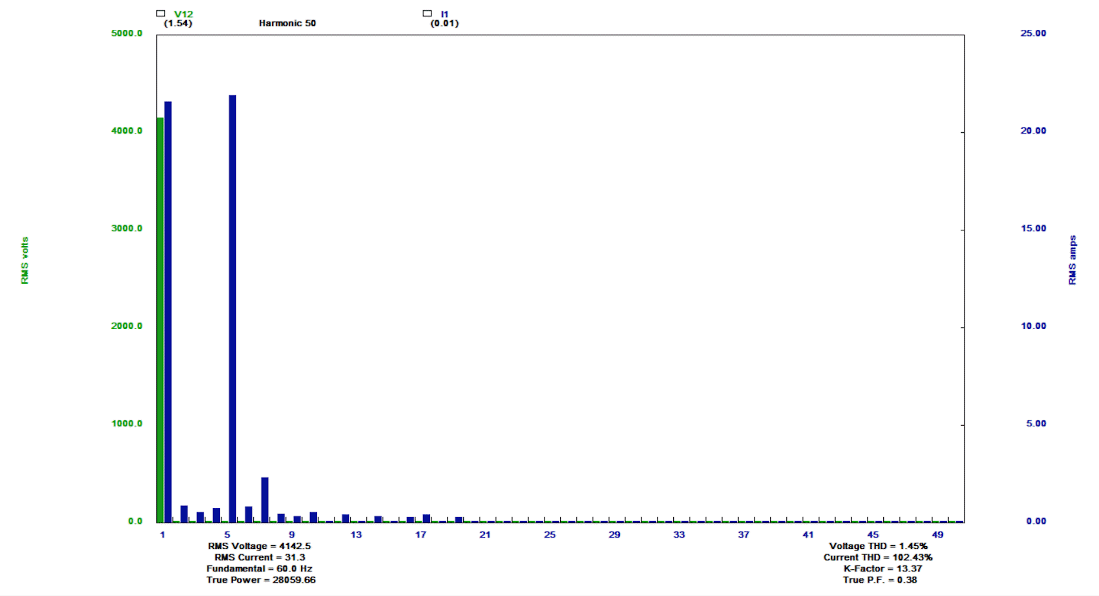
Fig. 2. The harmonics in voltage and current associated with Fig. 1,
including Total Harmonic Distortion (THD) Voltage and Current.
In Fig. 2, we see Voltage and Current data with the total voltage THD through the 51st harmonic being 1.15% of the 4160V application. Note that the Current THD is 59.86%, which is related to the distortion seen in the image at the start of this article (Fig. 1). Is this a failed harmonic condition?
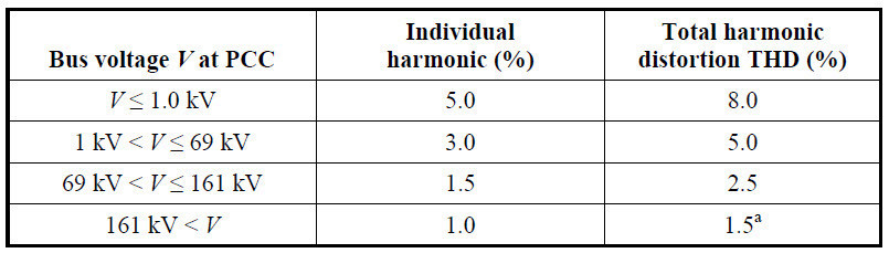
Fig. 3. PCC table from IEEE 519 Allowable Total Harmonic Distortion Voltage.
The Voltage THD limits are outlined in Fig. 3. In this instance, the maximum voltage THD is 5% with any individual harmonic needing to be less than 3%. However, Current, according to IEEE 519, is based upon Total Dynamic Distortion (TDD).
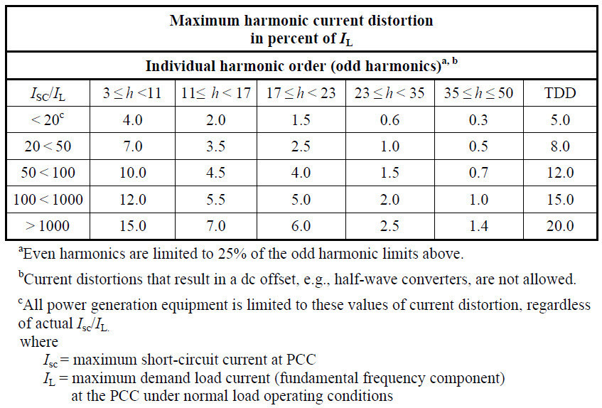
Fig. 4. Maximum allowable Current Total Dynamic Distortion (TDD) from IEEE 519 table.
Consider the following hypothetical commercial application where the PCC is the secondary of the branch transformer, as defined by specification:
If the Isc is 15,000 Amps and the normal load is 1,200 Amps, then the ratio would be 15,000A/1200A = 12.5, which would be the top row of the TDD chart. This means that the maximum TDD would be 5% and, as the majority of the Current harmonics are 5th and 7th, the max for these combined is 4%.
The TDD is then determined as the sum of harmonic currents divided by the normal peak load. In this case, (110A/1200A)*100% = 9.17%, which is outside both the 4% and 5% limits. This situation would require immediate correction.
It is important to note that Current TDD affects only the branch that is being fed, or that which is claimed in the standard. In actual experience, and depending on the loading of the power circuits, high current harmonics may affect other equipment within the same branch. Among the concerns with high harmonic conditions are impacts on electronics within the system and heating in transformers and motors.
CORRECTING HARMONICS
Harmonics can be corrected through the application of passive filters on drives and electronic devices, a sine-wave filter, or an active filter in the system.
- Passive filters can include inductors for current harmonics or a combination of inductors and capacitors for Voltage and Current harmonics. These are designed to smooth out the waveforms and are often found on both the input and output side of a VFD.
- Sine wave filters are similar to capacitive and inductive filters, except that they are usually on the output of a drive and make PWM (Pulse Width Modulated) Voltage output appear as a sine wave, reducing harmonic impact on the motor.
- Active filters inject a signal that’s 180 degrees out of phase with each harmonic to reduce harmonic effects into the supply. Another alternative is to select a ‘low harmonic’ drive, which may have a number of options including newer active front-end drives.TRR
ABOUT THE AUTHOR
Howard Penrose, Ph.D., CMRP, is Founder and President of MotorDoc LLC, Lombard, IL and, among other things, a Past Chair of the Society for Reliability and Maintenance Professionals, Atlanta (smrp.org). Email howard@motordoc.com or info@motordoc.com and/or visit motordoc.com.
Tags: Electric motors, drive, VFDs, power quality, electric power, electrical systems

