
One area that is extremely important to electrical reliability and operation of a plant is also one of the least understood. Unfortunately, some have taken advantage of that misunderstanding. This includes associating a reduction in current with reduced energy consumption, thereby suggesting that improving power factor will save energy costs. Let’s clear up some of the mystery around this issue.
Demonstrating a reduction in current with an ammeter before and after the application of a capacitor actually represents a closer relationship to useful energy, measured in kilowatts (kW), to the apparent measurement of kilo-Volt-Amperes (kVA).
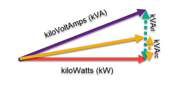
Fig. 1. Power factor representation
The true energy consumption of a system is measured in kW, or power, which is the useful conversion of one form of energy to another. Power factor can be represented by dividing the kW by the KVA to represent a percentage or decimal value between 0 and 1. The reason is that for a coil to maintain a magnetic field, it requires “reactive” energy provided, which is the kVArl, or kilo-Volt-Ampere-Reactive-Inductive. The greater the field required, the more current required to perform the same work, with work being measured in kW.
As capacitive reactance is 180 electrical degrees from inductance, if capacitance is added to the circuit, it introduces kVArc, or kilo-Volt-Ampere-Capacitive, which reduces the impact of kVArl. The danger associated with capacitive correction is that you can end up in a situation where the voltage lags current, resulting in the loss of voltage control. So, in environments where you have inductive loads, it is normal to have some level of lagging power factor in order to manage the system.
Because inductive loads and capacitive loads impact the power factor of a system, it becomes easy to imagine that making changes to either will impact the amount of current that is measured. This, however, does not impact the energy consumed (kW demand and kWh usage), which is how most utilities bill customers.
Misrepresentation of the change in current having an impact on energy consumption is often used by unscrupulous entities to sell “energy-saving” boxes, which usually consist of capacitors. More often than not, such products end up causing a leading power factor and damage to household or business electronics. If power factor at the point of connection to the utility is low enough, usually under 0.94 PFa (Apparent Power Factor), the utility may charge a power-factor penalty.
The changes in current do impact capacity of generators, transformers, and conductors within the system. While there are some parasitic losses (I2R) due to the higher current passing through conductors and resistive systems, they are negligible in most plants. The impact on the system involves “tuning” and “capacity,” where a poor power factor will cause harmonic conditions and other power-quality issues to become excessive, as well as cause properly sized conductors to heat, connections to heat/cool with the result of loosening, and transformers to heat and gas.
With excessively poor power factor, conductors and insulation systems within electric motors and other electrical and electronic equipment will overheat and fail.
APPARENT POWER FACTOR (PFa)
The power factor we are most used to discussing is “apparent power factor,” which is the power, in watts, divided by the rms (root-mean-square) Volts times the rms Amperes (kW/[[Vrms*Irms]/1000]). In a system that doesn’t contain significant harmonics, this calculation will be relatively accurate.
.
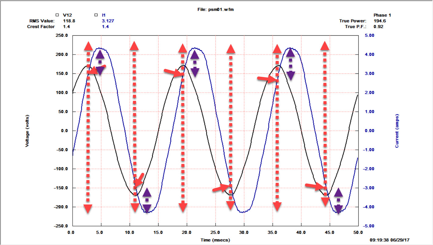
Fig. 2. Waveform of one phase Voltage and lagging Current
In Fig. 2, the black line is Voltage and the blue line is Current, with the red arrows identifying the point where the power required by the load resides. In effect, the peak load in kW is found under the peak Voltage, the lagging Current means that the power for that point requires more current to perform work (purple arrows).
The vectors for Fig. 2 are found in Fig. 3
.
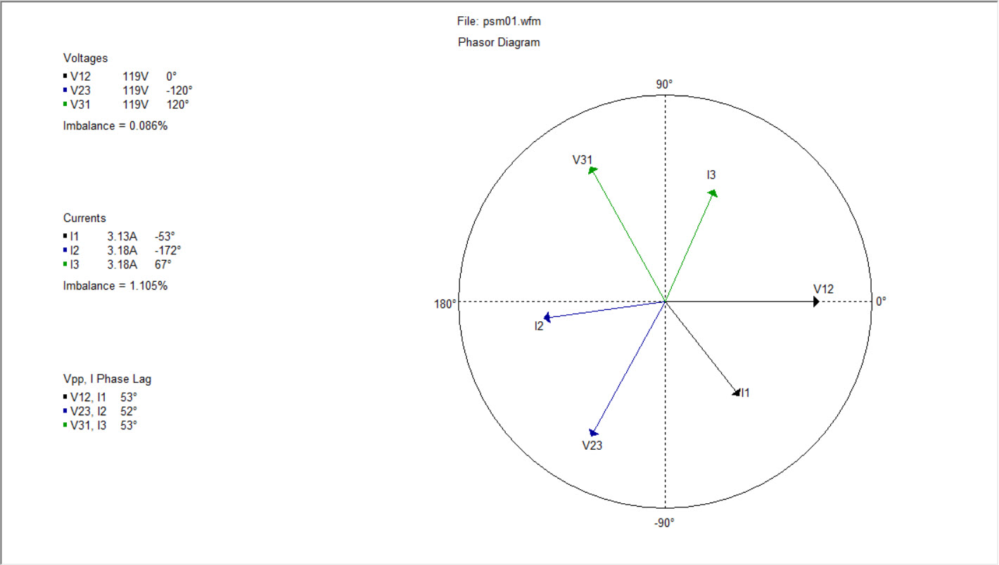
Fig. 3. Voltage and Current vectors for Fig. 2
The harmonics associated with Figs. 2 and 3 are found in Fig. 4.
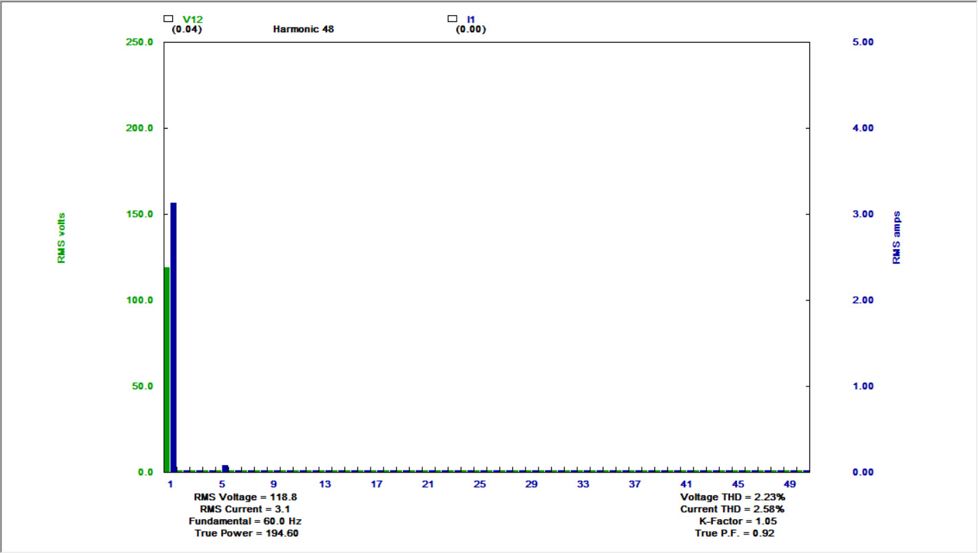
Fig. 4. Voltage and Current harmonics for Fig. 2
As noted, the imbalance in Fig. 3 is relatively low, and the harmonics shown in Fig. 4 have relatively low values, even though the THD (Total Harmonic Distortion) is relatively high. The information in Figs. 3 and 4 is important to ensure that we are looking at power factor correctly.
TRUE POWER FACTOR (PFt)
What is the impact if we have a heavy notching in either Voltage or Current that results in significant harmonic distortion, such as that found in Fig. 5? While this appears to be simply awful, in reality, for this system, the current harmonics are within acceptable values per IEEE Standard 519-2014. Since we will want to determine what the impact is on the system capacity, we’ll be using true power factor (PFt), which is the power factor taking all of the harmonics into account.
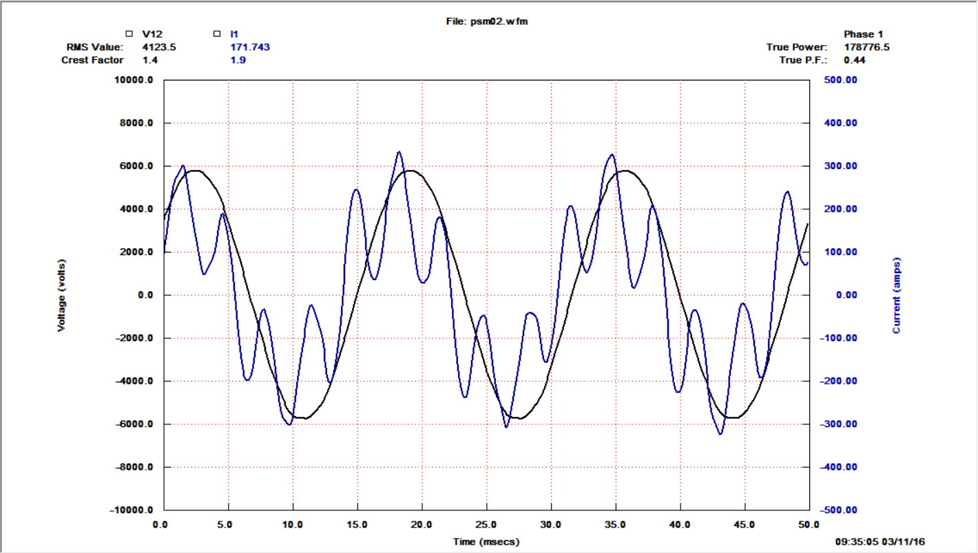
Fig. 5. Voltage and Current with heavy current-notching
and related 5th harmonic
The angles would appear as in Fig. 6 below, and the harmonics become important, as shown in the subsequent Fig 7.
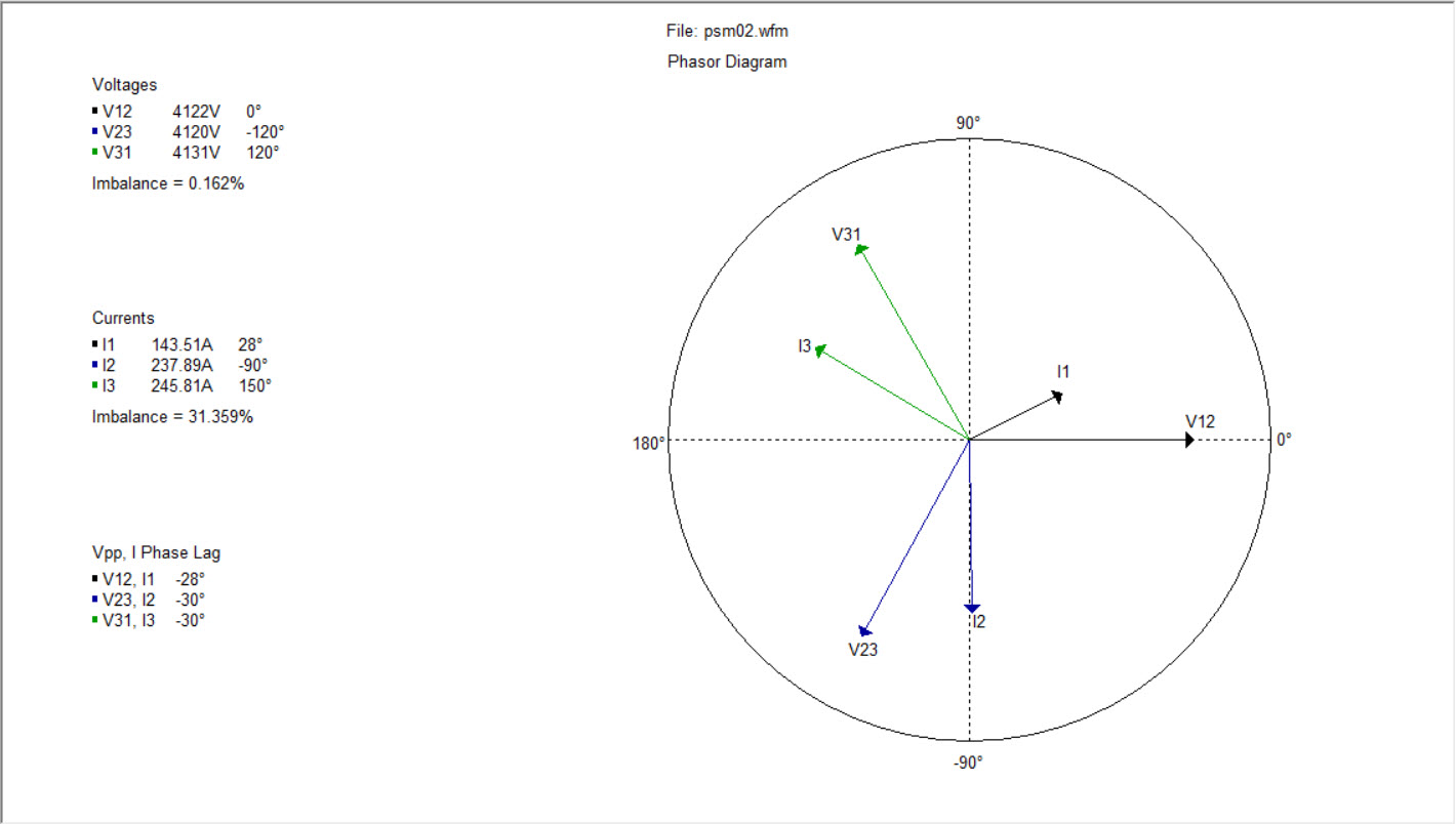
Fig. 6. Phasor diagram for Fig. 5
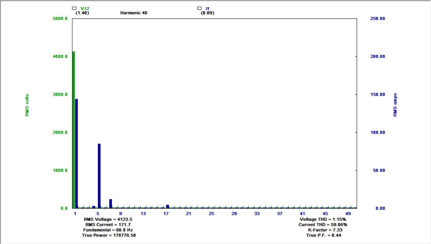
Fig. 7. Harmonics associated with Fig. 5
In Fig. 6, the Voltage is 120 electrical degrees apart, but the Current balance shows 31.36% unbalance. In this case, we have several issues that we will discuss in the next article related to harmonic distortion and system impact. For power factor, the PFt considers the Total Harmonic Distortion, or PFt = PFa*PFd (PFd is the Distortion Power Factor which is represented as PFd = 1/[SquareRoot[1+THD^2]]). As a result, a system as shown in Fig. 5 would have a PFa of 0.83, but the PFt is actually 0.44.
CORRECTION FOR POWER FACTOR CONCERNS
While we’ll cover some methods of power-factor correction in the next article, there are methods for correcting both PFa and PFt that can help address challenges in your electrical system. Impacts of correcting power factor include:
- Fewer loose connections found during infrared surveys;
- Improved voltage drop and starting times on electric machines and heavy electrical equipment;
- Improved harmonic distortion conditions;
- Improved thermal aging in electric motors, generators, transformers and cables;
- Fewer errors in IoT devices and PLCs;
- Fewer mechanical/bearing faults; and,
- Fewer electronic device failures.
For systems that have just PFa considerations, power-factor correction capacitors can be applied. We usually recommend that a power study be conducted before selecting the type of capacitor systems to be applied. There are a number of strategies, including capacitors at each electric motor, capacitor banks, or combination of the two. When used at the electric machines, this will decrease the impact on the internal systems, when used as a capacitor bank, it will correct the power factor upstream of the facility. A review of the internal conditions through the power study will help in making decisions.
Synchronous condensers or synchronous electric motors both operate in a similar fashion. In these cases, the excitation system is used to generate a leading power factor. It is important to remember that some synchronous motors will only generate a 1.0 PF and not a leading power factor for system correction.
Where there are severe-harmonic-condition corrections, such as with capacitors, difficulties can ensue. This includes a 5th harmonic condition that can result in failed capacitors, bulged capacitors, and even explosive failures.
In Figure 5, the unbalanced current was the result of failed capacitors due to the high 5th harmonic current. When high harmonic conditions exist, the use of corrective measures such as harmonic filters, which are passive circuits) and active filters, which inject an opposite harmonic to negate the harmonic conditions.
When applying variable frequency drives (VFDs) in a plant, check to verify what power-factor correction measures are in place. Modern VFDs will improve power factor and, if the harmonic conditions are good, may cause problems for systems that have highly corrected power factor in the system, or if the drives are going on the primary loads in the system.
CONCLUSION
Understanding power-quality conditions such as power factor can help you improve your facility’s electrical reliability. While the power factor doesn’t have a significant impact on your company’s energy costs, with the exception of low-power-factor penalties, usually for heavy industry, it does have an impact on your electrical capacity. Power factor also determines your electrical system’s “tuning” and how other disturbances and conditions will affect the system.
The difference between apparent power factor and true power factor are equally important given the fact that the way power factor is corrected is the direct result of the type of conditions that are present. For long-term electrical reliability, evaluating the electrical system as “electrical” and “electronic” devices, including IoT monitoring systems, computers, lighting, electric motors, drives, transformers and generators and their impact on the electrical system, is imperative.TRR
ABOUT THE AUTHOR
Howard Penrose, Ph.D., CMRP, is Founder and President of MotorDoc LLC, Lombard, IL and, among other things, a Past Chair of the Society for Reliability and Maintenance Professionals, Atlanta (smrp.org). Email howard@motordoc.com or info@motordoc.com and/or visit motordoc.com.

