
As industrial gas turbines began evolving from aircraft jet engines in the 1950s, the need for high-torque and/or higher-speed-capable flexible couplings became more evident. To keep pace, these shaft connectors were enhanced to achieve greater power density. Those types of enhancements (and other coupling improvements) have continued over time.
Increased power density of a coupling is best explained as the optimized combination of lighter weight and higher torque-transmission capacity. Early on, gear couplings were used because they have high power density. But they require lubrication and are unable to operate at ever higher speeds. While still in use in slow-speed machines and those that demand ruggedness, gear couplings no longer predominate. Nevertheless, with good maintenance practices and keeping gear couplings well lubricated, they can perform well.
For a while, designers could opt for either gear couplings or diaphragm couplings (Fig. 1). Diaphragm couplings were among the components that were carried over from aircraft applications, and several coupling manufacturers soon entered the commercial field. Progress was made in optimized sizing, superior coatings, and many other seemingly minor improvements. Taken together, these improvements resulted in diaphragm couplings ranking among the most reliable components in modern fluid machines.
Today, non-lubricated coupling designs represent highly suitable alternatives to gear couplings. Disc-pack and flexible-diaphragm designs are much preferred by today’s reliability-focused users. Although they differ from each other, both offer advantages in the applications for which they were designed.
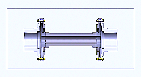 Fig. 1. Contoured diaphragm coupling.
The flexing element of a diaphragm coupling is a plate, or a series of adjoining plates, called the “diaphragm(s).” These diaphragms accommodate misalignment and transmit torque using the metal between the outside and inside diameters of the diaphragm. Its cross-section is contoured to keep stresses well within acceptable limits. These stresses result from the slight but unavoidable misalignment (or skew) between driving and driven shafts. All coupling designs must incorporate a measure of flexibility to accommodate slightly out-of-parallel and/or skewed angular alignment between equipment shafts.
Our recommendation is for reliability engineers to examine spare parts usage at their facilities. In many cases, the next spare part for a large turbotrain should be a non-lubricated coupling. There is, however, one caveat: A computerized analysis of the rotor-bearing system must be performed to verify that the lateral and torsional stabilities are within acceptable limits. This verification should be done prior to upgrading large fluid machinery trains with these superior couplings.TRR
Editor’s Note: Click Here To Download A Newly Updated List Of Heinz Bloch’s 24 Books
ABOUT THE AUTHOR
Heinz Bloch’s long professional career included assignments as Exxon Chemical’s Regional Machinery Specialist for the United States. A recognized subject-matter-expert on plant equipment and failure avoidance, he is the author of numerous books and articles, and continues to present at technical conferences around the world. Bloch holds B.S. and M.S. degrees in Mechanical Engineering and is an ASME Life Fellow. These days, he’s based near Houston, TX.
Tags: reliability, availability, maintenance, RAM, diaphragm couplings, gear couplings, disc-pack couplings, bearings, rotor-bearing systems, gas turbines

