
In ball-bearing machines, the bearings are often cited as the primary cause of electric-motor failure. There are numerous lubrication and application issues that impact bearing life, as well as basically cause reduced life. While we will continue to return to the topic of bearings in this ongoing series on your electric motors, here the focus is on the impact of rotor balance.
There is a direct correlation between the vibration and unbalance of an electric machine and the bearing life and reliability of the machine. In this article, we will review several instances of a rotor-only unbalance on bearings leaving out the attached components, thrust, load, thermal, and environmental considerations in the life of the bearing on a machine.
We will assume that all of these conditions are the same and review only the L10 life of the bearings and the impact of direct unbalance. In addition, we will compare the L10 life of the bearing only assuming the weight of the rotor and perfect balance versus the standard G2.5 balance based upon ISO Standard 1940-2003.
THE CALCULATIONS
The L10 life of a bearing is the calculated value at which a population of 10% of bearings will fail. This value is calculated using Eq. 1 and assumes a perfect environment.
L10 = (1,000,000/(RPM*60))*(C/P)^r (Eq. 1)
Where rpm is speed, C is the catalog dynamic rating of the bearing, P is the effective load, and r is 3 for ball bearings and 3-1/3 for all other types. It is important to keep all data in the appropriate form, such as we will use “lbs force,” instead of Newtons in this article.
ISO Standard 281 further identifies the calculated life/reliability of the bearing by including modification factors (Eq. 2), which are used to include the operating environment.
Lnm = a1*aISO*L10 (Eq. 2)
Lnm is the life rating, a1 is the multiplier based upon the percent surviving bearings, and also involves environmental and lubrication influences. For the purposes of this article, we are going to represent both multipliers as ‘1’ such that they do not have an impact on the purpose behind this discussion.
The P, or effective load, on the bearing is calculated several ways. One is the weight of the rotor on the bearing (basically, half the rotor weight across two bearings) and the rest are loads based upon other components attached to the shaft, unbalance, misalignment, belt tension, etc. For our purposes, we are only going to explore the rotor weight and unbalance impact and use one bearing on the rotor as an example.
We often hear of vibration in terms of mils (displacement), in/sec (or mm/sec – both are velocity), or g (acceleration). In the case of determining the amount of force due to unbalance alone, you need to determine the pound-inch (lb-in) unbalance of the motor and attached components. This can be calculated as shown in Eq. 3, where Flbs is force in pounds.
Flbs = 1.770*(rpm/1000)^2*lb-in (Eq. 3)
Therefore, an 1800 rpm rotor with 1/16th lb unbalance and a diameter of 24 inches (12-in. radius) would have a radial force of 68.76 lbs.
This force (Flbs) is then multiplied against a constant that can be added to the forces calculated for the L10 life of the motor. In effect, the additional value to add to the weight of the rotor for P is Flbs*1.333, or for the example above, P = 91.45lbs. If this rotor is 200 lbs, then the life reduction can be calculated by comparing the bearing life before and after by adding the additional force for a second calculation and noting the difference.
The rotor shown in Fig. 1 is actually vertically mounted, leading to the use of larger bearings to handle high axial thrust versus radial loading. For the purpose of this example, we will calculate the bearing life and impact based upon the rotor being horizontal and the load being primarily radial.
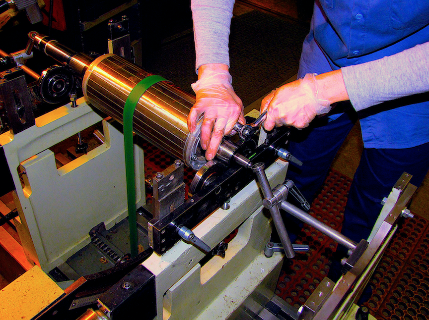
Fig. 1. This rotor is vertically mounted. To handle high axial thrust versus radial loading, the bearings are larger.
The rotor weighs 265 lbs, with a motor speed of 3560 rpm. The bearings are each 6316 ZZ bearings with a C dynamic loading of 27,427 lbs. The acceptable G2.5 unbalance, per the ISO 1940- 20032 is 37 gram-inch, and the as-found was 98.3 gram-inch. Upon completion of balancing the final balance was 0.382 gram-inch. For purpose of the calculation, all information was converted to pound-inch (lb-in). The rotor is 8.25 inches in diameter (4.125-in. radius).
If we assume that conditions are such that an average bearing operates for five years in specific conditions, and those conditions are the same when we compare the three different results, we have the following table based upon the calculated L10 life.
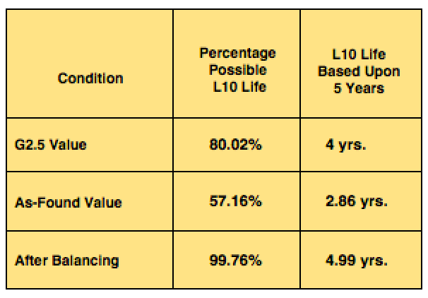
Table I: L10 Comparison with Unbalance
BOTTOM LINE
As noted, the potential life of an electric machine’s bearings is significantly improved with precision balancing of the motor. With bearing failures making up more than 53% of motor-reliability issues, balancing alone, can improve the overall reliability of your system and, as a result, decrease your maintenance costs.TRR
ABOUT THE AUTHOR
Howard Penrose, Ph.D., CMRP, is Founder and President of Motor Doc LLC, Lombard, IL and, among other things, a Past Chair of the Society for Reliability and Maintenance Professionals, Atlanta (smrp.org). Email him at howard@motordoc.com, or info@motordoc.com, and/or visit motordoc.com.
Tags: motors, drives, electrical systems, voltage, power systems, reliability, availability, maintenance, vibration, balancing, alignment, bearings, reliability, availability, maintenance

