One of the least understood, yet critical, components of power quality is the grounding system. While we cannot cover all variations of these systems, it’s important to note that the primary methods are grounded/bonded; resistance ground; and, ungrounded/floating.
In most texts and standards, grounding is often managed as its own science and not just part of the power quality context. Ground is basically your reference point for voltage and, when there are issues, can result in some unusual conditions that can range from bearing failure to catastrophic winding failure and even personnel safety. Because of the complexity of this topic we will discuss grounding issues in the motor system over the next several articles.
The purpose for grounding the system is threefold: 1) to direct stray current and voltage away from equipment systems and personnel should a fault occur; 2) allow for fault-detection sensing; and 3) set the reference point for voltage. In effect, voltage is electrical pressure and requires a reference point with the resulting difference being the potential.
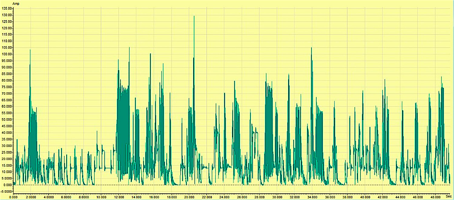
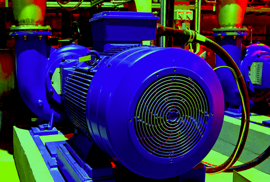
Ground noise during motor startup on a high-resistance grounding system.
(CLICK HERE TO VIEW LARGER VERSION)
It is quite possible to have multiple references in a facility such that if the ground in the motor-control center (MCC) is “0” and the reference to the MCC ground in the machine room is 100 V, there are ramifications. For instance, if a VFD is grounded in the MCC and a 460 Vac-RMS volt motor is grounded in the machine room and 460 Vac at 60 Hz is supplied from the VFD, the insulation system would see a shifted peak such that, at the top, the value would be +360 Vac, and the bottom would be -560 Vac. The peaks of the pulses would be higher, meaning that the winding stress on the negative side would be as high as 792 V-peak. This would generate problems for motor operation and insulation-system integrity. The result is that motor and drives are normally grounded to a common point.
The issue becomes even more complex as we start referencing other grounding systems that have their own specific applications. The three most common types in industry are bonded systems, high-resistance grounding systems, and low-resistance grounding systems. Bonded systems provide a direct path to earth ground, but have a greater potential when arc flash or ground faults occur. The resistance grounding systems limit the current flow when a fault occurs, resulting in lower arc flash energy. It is important to size resistance grounding systems correctly so as to limit the current and potential on the frame of electric motors and other electrical systems.
The type of potential on ground will have an effect on equipment, as ground is rarely a constant, especially with the increasing population of electronic devices. The result can be an ebb and flow of potential to fast-rise time impulses that are damaging to insulation systems in the same way as if they were operating on a VFD or suffered a ‘lightning strike.’ Consider this example of a submersible pump grounded to a pipe during a storm: An impulse from a lightning strike travels through the pipe and pierces the insulation system causing the motor to ground.
Part II of this grounding series will discuss quick methods to test and evaluate the condition of your ground system.TRR
ABOUT THE AUTHOR
Howard Penrose, Ph.D., CMRP, is Founder and President of Motor Doc LLC, Lombard, IL and, among other things, a Past Chair of the Society for Reliability and Maintenance Professionals, Atlanta (smrp.org). Email him at howard@motordoc.com, or info@motordoc.com, and/or visit motordoc.com.
Tags: motors, electrical systems, grounding systems, voltage, power systems, power quality, electrical safety

