In most of my articles, the terms Electrical Signature Analysis (ESA) and Motor Current Signature Analysis (MCSA) have been interchangeable. There are, however, differences in how the in-depth analysis of both voltage and current views the system versus just the use of current. In this article, we are focusing on how both of these approaches provide information on the condition of electrical-insulation systems.
There are signatures that identify the degradation of the insulation system primarily in the case of turn-to-turn faults. Until the later 1990s and early 2000s, the term MCSA was used for both ESA and MCSA including within patents and patent applications, articles, and journals. In 2013, ISO 20958, “Condition Monitoring and Diagnostics of Machine Systems – Electrical Signature Analysis of Three-Phase Induction Motors,” clarified the definitions.
The first mention of the detection of winding shorts using current signature analysis was a 1982 Institute of Electrical Engineers (IEE) Conference paper titled, “An Electrical Method for Condition Monitoring of Motors,” by Steele, Ashen, and Knight. Other than a brief discussion referencing spectral analysis of current data, the paper didn’t contain many significant details. The mathematical treatment of how to arrive at the signature was presented in July 1985, in the IEEE (Institute of Electrical and Electronics Engineers) Transactions on Power Apparatus and Systems paper, by Williamson (London, UK) and Mirzoian (Armenia, USSR), “Analysis of Cage Induction Motors with Stator Winding Faults.” Those cited papers/publications were in parallel with W. T. Thomson’s work on the development of MCSA for offshore drilling platforms at The Robert Gordon University (Aberdeen, Scotland) in the 1980s and work by Harold Haynes at Oak Ridge National Labs (Knoxville, TN, USA) on ESA during the same period.
Through the 1990s, a number of papers related to the detection of winding shorts and related current signatures had been presented through IEEE (with the primary studies and experiments having been performed on motors with induced winding shorts or through simulation). It was not until 2001 that W. T. Thomson discussed the concept of the detection of winding degradation versus a full winding short at the 2001 International Conference on Power Electronics, Machines and Drives. In that Conference presentation (titled “On-Line Diagnosis of Stator Shorted Turns in Low Voltage Stator Windings of 3-Phase Induction Motors Prior to Failure”), Thomson stressed the importance of continuous monitoring due to how rapidly winding degradation failures occur.
In 2020, I presented an IEEE Electrical Insulation Conference paper, “Evaluation of Stator and Rotor Interturn Stress with Electrical Signature Analysis in Variable Frequency Drive and Wind Generator Applications.” In that paper, the primary focus was on the ability to detect winding stresses in inverter applications prior to winding failure; the ability to mitigate those types of failures; and what the test results identified.
As I noted, in the case of VFD-driven equipment, the use of either MCSA or ESA will detect the stresses associated with degradation. However, ESA also allows identification of the watts losses associated with a defect, as well the defect’s severity, especially when performing data collection routes versus continuous monitoring. When identifying winding stress in line frequency applications, ESA is more important in determining if the data is originating in the tested machine or another piece of equipment elsewhere in the same branch.
The terms “degradation” and “winding stress” are not interchangeable: “Degradation” assumes a direct measurement of the defect that is occurring. “Winding stress” indicates the driving force behind winding degradation. This means that when we using the winding-stress approach, the indicator is the detection of the electrical or magnetic forces that cause degradation; it is not a direct measurement of degradation. Direct measurements would include those for ground current, which would also be indicators of other conditions.
One of the challenges within the testing industry and its relationship to reliability and asset management is the concept that we must find defects and sometimes project remaining useful life (RUL). Reliability engineering, though, is the practice of effectively wringing out every available measure of return on investment for the equipment, process, or system cost effectively. The ability to detect the driving forces for equipment degradation is more suited to reliability than the detection of a fault such that mitigation options can be determined and implemented.
As noted in my referenced 2020 paper (Evaluation of Stator and Rotor Interturn Stress with Electrical Signature Analysis in Variable Frequency Drive and Wind Generator Applications – MotorDoc LLC), the detection of winding stress is often incorrect variable frequency drive settings. Simply changing the settings to match the motor and, in cases where the drive is operating at something other than Volts/Hz, performing several auto-tunes, will correct the primary degradation forces. In those cases where this step does not correct the winding stress, additional investigation is necessary in a similar way as across-the-line equipment.
For across-the-line motors and generators, the identification of winding stress is still an indicator that something is disturbing the airgap magnetic field associated with discharges between conductors or ground. If we are evaluating this condition on an electric motor or generator above 6,000 Volts, and sometimes at 2300 or 4160, one of the causes can be Partial Discharge (PD) or corona. Other conditions can be severe contamination or slot-sparking to the frame. These conditions would be confirmed through other inspections or tests with ESA providing the alert with the exception that when a stator slot signature exists along with a winding stress signature, the defect is severe.
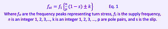
The signature for winding stress is shown as Equation 1 (below) with a full treatise on the theory behind the formula found in “Analysis of Cage Induction Motors with Stator Winding Faults,” found on IEEEXplore.ieee.org (Analysis of Cage Induction Motors with Stator Winding Faults | IEEE Journals & Magazine | IEEE Xplore).
The methodology has proven to be an excellent practice for the commissioning of variable frequency drive applications as well as part of continuous monitoring programs to trigger offline winding tests.
CONCLUSION
One of the earliest concepts surrounding MCSA and ESA was the detection of winding defects and degradation in electric motors. Practical application and investigation have shown that the indicators are winding stresses resulting in partial discharges, sparking, or other current crossing between conductors or conductors to ground, that affect the magnetic field between the stator and rotor. Instead of a direct measurement of degradation, ESA identifies the driving force behind insulation degradation, often providing the opportunity to mitigate conditions before a fault occurs.TRR
ABOUT THE AUTHOR
Howard Penrose, Ph.D., CMRP, is Founder and President of Motor Doc LLC, Lombard, IL and, among other things, a Past Chair of the Society for Maintenance and Reliability Professionals, Atlanta (smrp.org). Email him at howard@motordoc.com, or info@motordoc.com, and/or visit motordoc.com.
Tags: reliability, availability, maintenance, RAM, Electrical Signature Analysis, ESA, Motor Circuit Signature Analysis, electrical systems, electric motors, motor insulation, motor windings, predictive maintenance,

