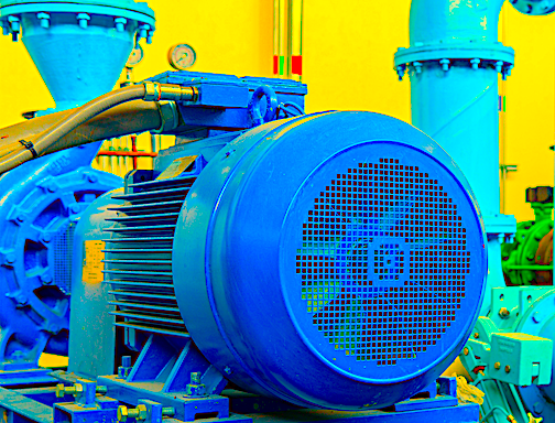
Rotor defects are the most strenuously investigated areas related to Current and Electrical Signature Analysis (ESA). Air-gap eccentricities are the second. What’s interesting is that the rotor-defect issues are one of the least-expected causes of failure for a majority of electric motors and generators. A great many common electric machine, coupling, and driven equipment faults are detectible through air-gap eccentricities by comparison.
Note, however, that most available literature concentrates on the identification of air-gap defects, not the types of faults associated with them and the impact on remaining useful life and energy consumption. In this series, we start by defining air-gap eccentricities, then discuss examples of how they are applied, and finally show how to utilize the values to determine Remaining Useful Life (RUL) or Time to Failure Estimation (TTFE).
SOME BACKGROUND
Air-gap eccentricity is made up of two types of conditions, referred to as static and dynamic. Static eccentricity is where the air gap is constant to one side of the stator, while dynamic is where the air gap rotates with the running speed of the rotor. These conditions are often modeled as the rotor located off-center in the stator bore for static eccentricity, and the rotor orbiting for dynamic eccentricity.
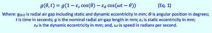
In most published troubleshooting methods, it’s assumed that the rotor is physically out of place for different machine defects. However, the true condition being evaluated is the air-gap magnetic field. This means that the defect is actually not the physical position of the rotor, but rather the magnetic position within the machine’s air gap. These are modeled as Equation 1:
The measurement and frequencies associated with eccentricity are based upon the nominal air gap and the force associated with the Unbalanced Magnetic Pull (UMP) measured in Newtons of force as shown in Equation 2:
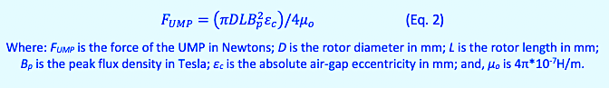
The force works against the stiffness of the rotor shaft and rotor to effect movement, mechanically, within the air gap. Should the UMP exceed the shaft stiffness, the rotor may come into contact with the stator causing a failure.
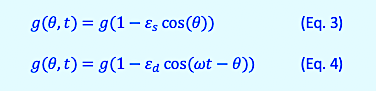
When reviewing the different types of eccentricity, the effective value for the other type of eccentricity is ignored such that static eccentricity is measured as Equation 3, and dynamic eccentricity is measured as Equation 4.
What does this mean? It means that it’s possible to determine the extent of eccentricity if certain information is known. That information includes the air gap, rotor, shaft stiffness, and operating context.
An excellent discussion associated with this can be found in William Thomson and Ian Culbert’s book, Current Signature Analysis for Condition Monitoring of Cage Induction Motors (Wiley Press, 2017), which is the reference we are using for this article, as well as for the relationship to Current Signature Analysis spectra associated with discussed issues.
While the Thomson and Culbert text follows the same direction as most technical papers on the subject related to mechanical placement of the rotor only, it does outline the point where conditions cause eccentricity peaks to appear. The point at which peaks begin to show significant peaks is when the static eccentricity passes 5% and the dB peaks increase as the severity of the eccentricity increases. Dynamic eccentricity starts to show at similar values, when solely present.
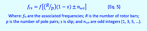
Another consideration is that static eccentricity shows up as specific spectra and dynamic eccentricity shows as different spectra. However, a combination of significant static and dynamic eccentricity will develop both values. The peaks associated with static eccentricity are found as Equation 5:
This translates out to Equation 6, where fn is the running speed in Hz:
![]()
Dynamic eccentricity is calculated as Eq. 7:
![]()
Now that we know what the frequencies are that we are reviewing for spectra with dB values greater than +10 dB above the noise floor or -65dB from the peak current (motors) or voltage (generators). With dynamic eccentricity, the running speed sideband peaks around the static eccentricity peaks would be +5 dB above the noise floor or -70dB down.
COMING UP
In the next installment (Part II) of this new series, we will begin to explore the patterns associated with static and dynamic eccentricity and what those patterns identify as equipment faults. The true power of ESA resides in the ability to look at spectra patterns in order to determine the type of faults that exist or the forces that are driving failures.TRR
ABOUT THE AUTHOR
Howard Penrose, Ph.D., CMRP, is Founder and President of Motor Doc LLC, Lombard, IL and, among other things, a Past Chair of the Society for Reliability and Maintenance Professionals, Atlanta (smrp.org). Email him at howard@motordoc.com, or info@motordoc.com, and/or visit motordoc.com.
Tags: motors, drives, generators, wind turbines, motor testing, air gap eccentricities, static eccentricity, dynamic eccentricity, air gap defects, air gap faults, rotor defects, reliability, availability, maintenance, RAM, electrical signature analysis, ESA, current signature analysis, CSA, motor current signature analysis, MCSA, vibration analysis

