Getting out in the field as part of research on electric-motor life cycles, remaining-useful-life (RUL) studies, (Time to Failure Estimation (TTFE), or as we refer to it, predictive maintenance (PdM), you get to study machines in many conditions. In this short case study, we discuss a pumping system that wasn’t just located at a remote site: It had not operated in two years.
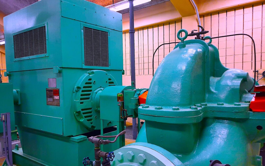
While our focus here is on testing of the 800-hp, 4,160 Vac, 1,180-rpm motor shown in the feature image at the top of this page (referred to as “Fig. 1” elsewhere in the article), we’ll also take a look at the driven pump. In conjunction with the article, we posted our feature image on LinkedIn and asked how others would start such a machine that had sat idle for as long as this one did. We noted that some responses/respondents made assumptions that, in turn, were out of context for the application.
The space where the referenced pump and motor are located is relatively clean. In fact, the building is tight enough that no significant dust was found on the motor. Although not occupied, the building is heated, even in winter, and rodent and bug protection systems are in place.
The first step in our testing involved an electrician opening the starter/disconnect and performing a quick insulation check. In the effort to connect our Electrical Signature Analysis (ESA) equipment, we asked for and received drawings of the motor from the client. We soon realized that said drawings didn’t match the cabinet. So, we simply connected current clamps to the back of the ammeter rotary switch on the starter and set the appropriate CT ratio in the ESA software.
One response regarding the photo we posted on LinkedIn (this article’s feature image/Fig. 1) alluded to the type of bearings in the motor. While the photo doesn’t provide a full view of the end-shield, there are no oil fittings on the bearing housing. The bearings are 6324 single-row ball designs with grease fittings. We used a pipe wrench and pipe to rotate the shaft the first time to “break away” expected dried grease and any oxidation. Once that was done, it was noted that the rotor moved to its original position even connected to the pump. The pump-bearing oil levels were checked, and oil cups filled.
General visual inspections showed that the motor was in visibly good condition. The ESA device was then set up to capture startup data automatically, and all personnel were moved away from the unit.
As shown in Fig. 2 below, a reduced-voltage soft start performed as required. There is, however, a current unbalance. That’s not an unusual condition, even in a motor of this size, especially when it involves a remote pumping station. Small current unbalances of this type are often the result of voltage or circuit unbalances and not necessarily a defect in the motor.
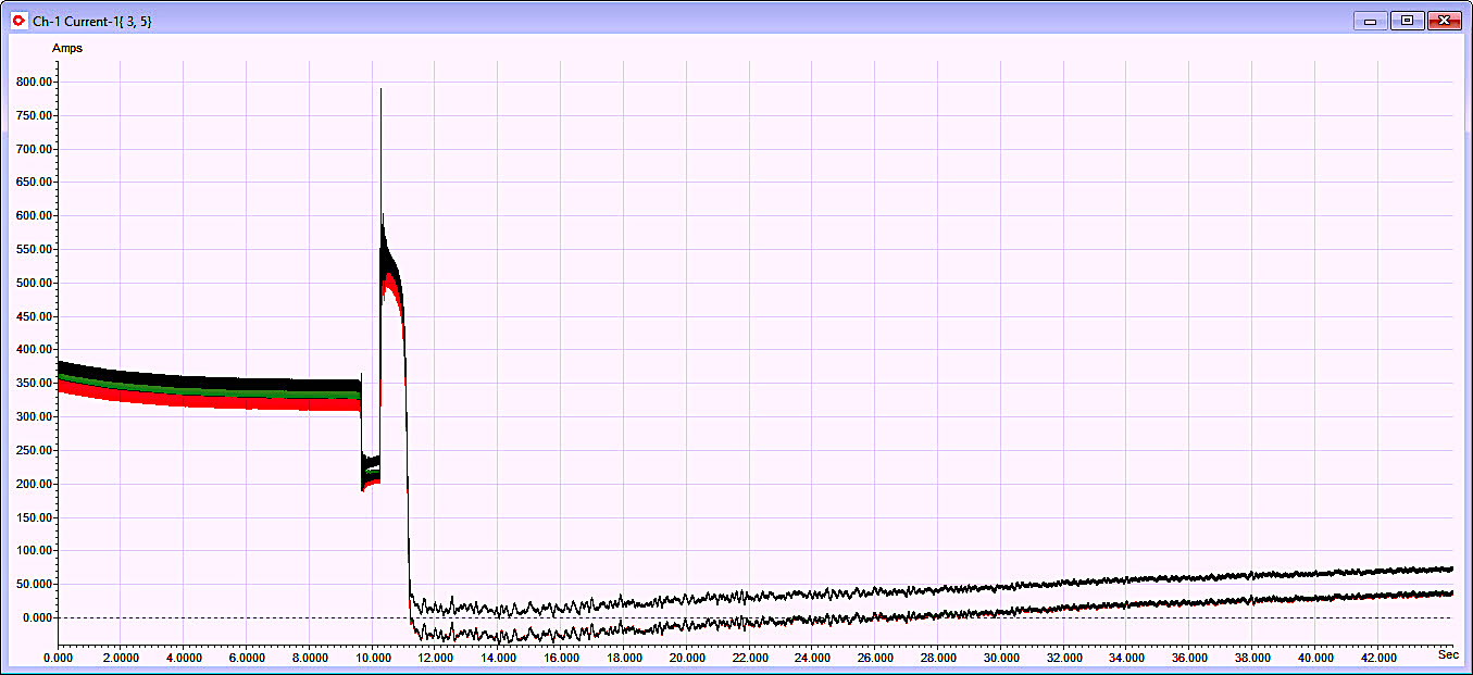
Fig. 2. The motor had a reduced voltage-starting system
that transitioned at 10 seconds.
As noted in Fig. 3, the speed time the bearing multipliers include some very low-level peaks associated with dried grease and possible false brinnelling. There are no roads or heavy-equipment operation near by, but other pump-systems are housed in the same building. Although we estimated the bearings to be in “OK” condition, we still recommended that they be replaced (best), or at least be flushed with new grease.
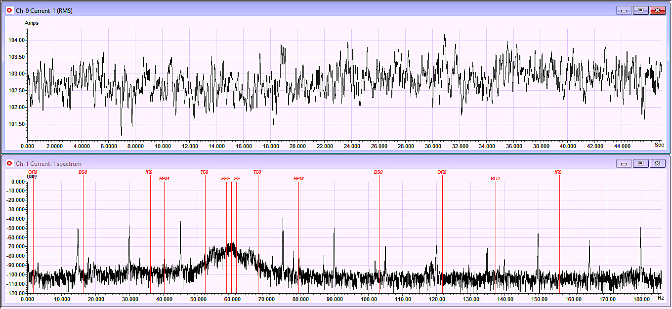
Fig. 3. Cavitation, low-level bearing signatures, slight unbalance.
Without a baseline, it’s challenging to determine if a stator mechanical peak is the result of the machine sitting idle for a length of time or is inherent in the machine. Sometimes, if the coil ends are too long and not properly anchored, the stator mechanical signature, as shown in Fig. 4, is observed. Other times, missing wedges, loose-stator-frame to core, coil movement, or other conditions would cause the stator mechanical signature. When working on the bearings. an inspection of the windings can be performed, as some of the access covers will be removed.
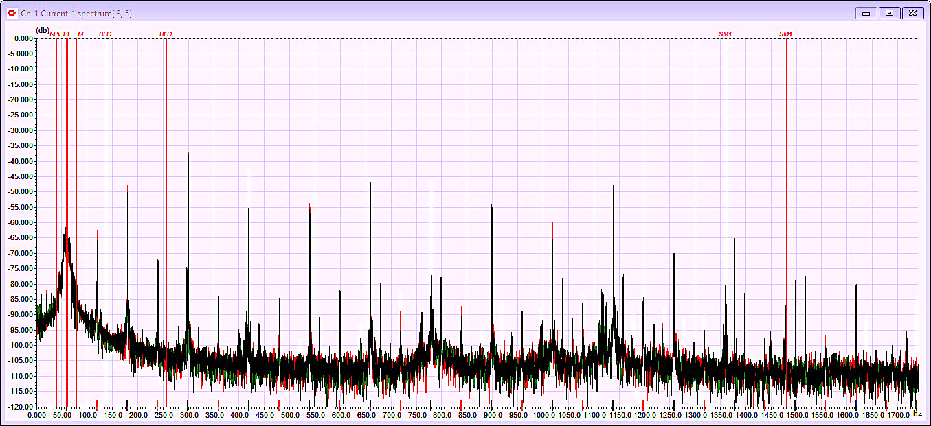
Fig. 4. Large stator mechanical peaks.
When a large motor sits idle for months or years, the rotor will tend to sag. One of the signs that this has occurred is when the rotor is turned and let go. If it returns to the original spot, the motor will have a slightly bowed shaft that will result in dynamic eccentricity, as shown in Fig. 5. Combined with the small 1X running speed peaks in Fig. 2, this means that the rotor is physically orbiting in the airgap.
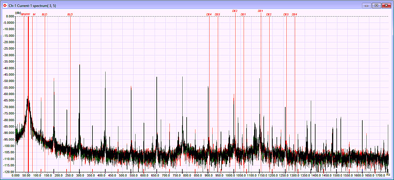
Fig. 5. Small dynamic eccentricity peaks associated with
rotor orbiting due to the shaft saggingafter
several years in the same position.
When both static and dynamic eccentricity are present, as found in Fig. 6, we have what is termed as “mixed eccentricity.” In this case the machine is operating off to one side in the machine and orbiting. The static eccentricity portion tends to be the result of poor assembly practices and will manifest if the rotor is off-center by more than ~10%.
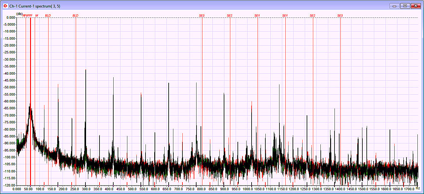
Fig 6. Static eccentricity peaks with dynamic eccentricity
identify “mixed eccentricity.”
When both static and dynamic eccentricity are present, as found in Fig. 6, we have what is termed as “mixed eccentricity.” In this case the machine is operating off to one side in the machine and orbiting. The static eccentricity portion tends to be the result of poor assembly practices and will manifest if the rotor is off-center by more than ~10%.
Overall, despite sitting idle for two years, the motor in this case study motor was in relatively good condition, all things considered. While occasional shaft rotation would have eliminated several of the existing conditions, the steps to correct them are not particularly challenging. For instance, it would be good practice to simply replace and regrease the motor bearings. The same holds true for the pump bearings. As for the static and dynamic eccentricity, it is also reasonable practice to attempt to run the motor and see if the conditions will correct during operation. If the dynamic eccentricity disappears and the static eccentricity is still present, use the access ports to check the air gap.TRR
Click Here To Read More About Idled-Equipment Issues In Heinz Bloch’s Article
“Part 2: Strategies For Short-Term Equipment Preservation”
ABOUT THE AUTHOR
Howard Penrose, Ph.D., CMRP, is Founder and President of Motor Doc LLC, Lombard, IL and, among other things, a Past Chair of the Society for Maintenance and Reliability Professionals, Atlanta (smrp.org). Email him at howard@motordoc.com, or info@motordoc.com, and/or visit motordoc.com.
Tags: reliability, availability, maintenance, RAM, electric motors, pumps, bearings, Electrical Signature Analysis, ESA

