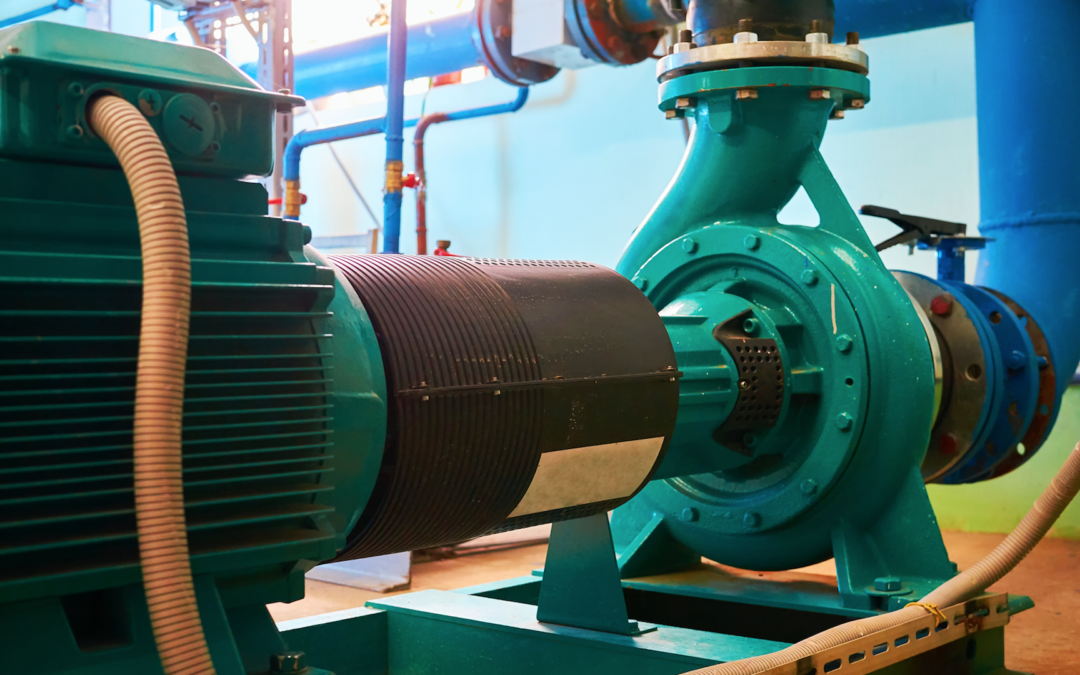
Those who deal with rotating-equipment maintenance are well aware that ensuring long equipment service life requires rotating elements to be balanced to minimize vibrations. There are a number of reasons for this.
High vibrations in rotating equipment can damage bearings, bushings, thrust collars, packing, seals, packing, and other important components. Further, high vibrations in one piece of equipment can damage nearby equipment that may otherwise be operating smoothly when those vibrations are transmitted through a common shaft, a coupling, connected piping, or a common mounting base.
UNDERSTANDING STATIC AND DYNAMIC UNBALANCE
To keep vibrations low, two types of unbalance in rotating equipment are commonly minimized: static and dynamic.
Static balance is achieved when the mass distribution around an element’s rotational axis is distributed such that if the rotating element were balanced through its axis or at its center point while not rotating, the element would not tip in any direction. This is similar to the static balance exhibited when a vinyl record or dinner plate is balanced on the point of a person’s finger.
In automobile-repair shops, for example, tires used to be statically balanced on a bubble balance. The tire would be positioned horizontally and centered on a vertical mandrel.
The mandrel also had a bubble level in its center. If the bubble was not in the center of the level and indicated that the tire was tilting in some direction, the mechanic would add lead weights to the rim of the tire until the bubble became centered and the tire did not tilt in any direction. When the bubble indicated the tire was resting level, it meant that the tire was reasonably statically balanced.
That method of balancing a rotating element, such as an automobile tire, was fine if the tire was basically thin enough to be considered a single plane. But, when it came to items with two or more planes of mass distribution, such as found in modern tires or multi-stage boiler-feed-water pumps, achieving a static balance, no matter how precise, was found to be insufficient to minimize vibrations. This is because while two planes of distributed mass might be balanced statically, when the element is rotated, vibrations may still occur due to opposing centrifugal forces, heavy spots in each plane, and the distance between the planes.
A heavy spot on one plane that is statically counterbalanced on the other plane, perhaps 180 degrees away (as seen from the end view of the shaft), will develop a moment when the element rotates because the two heavy spots develop centrifugal forces in opposite directions. Depending upon the distance between these centrifugal forces, a moment perpendicular to the rotating axis develops when the element rotates. This moment then causes vibrations as it spins periodically through 360 degrees. Typically, the nearby bearings or bushings bear the brunt of the resulting vibrational forces.
As a means of dealing with this rotational effect and minimizing vibrations, rotating components are routinely balanced on a stand that rotates the element and checks for resulting centrifugal forces due to heavy spots in the element’s various planes. O.E.M. and repair shops typically have balance stands and employ personnel trained in multi-plane dynamic balancing techniques to operate them.
To effect balance, a single-stage pump, for example, typically has its impeller mounted on its corresponding pump shaft, and together, the impeller and shaft are spun up on a balance stand. Measurements of the centrifugal-force vectors are made while the pump shaft and impeller are spinning. Small weights are then added in various locations, or, perhaps, a small amount of weight might be removed by grinding in various locations. The shaft and impeller are then spun up again to check the results.
This process is repeated several times, until the shaft and impeller spin with minimal vibrations. O.E.M.s and repair shops often provide a certificate that 1) attests to the fact that the rotor has been balanced; and 2) indicates the remaining residual imbalance.
The preceding method is normally sufficient for detecting and correcting both static and dynamic unbalance in a rotating element due to any small asymmetric distribution of mass within the element. There is, however, a third type of unbalance (hydrodynamic) that can occur in pumps, especially large ones that have been repaired several times. And hydrodynamic unbalance is not correctable using a balance stand. In fact, use of a balance stand to minimize vibrations can hide this type of unbalance.
UNDERSTANDING HYDRODYNAMIC UNBALANCE
Hydrodynamic unbalance occurs when the symmetrically arranged blades of a propeller type pump thrust unevenly. The following example shows how that can occur.
Consider a large, mixed-flow single stage pump, sometimes called a propeller pump, that has five blades. When the pump is manufactured, all five blades are arranged symmetrically around the center axis of the pump shaft, and all five blades have the same blade profile, dimensions, attack angle, and so on. When the pump is operated, all five blades produce equal thrust and pump liquid equally.
Figure 1 depicts the hypothetical thrust produced by each blade of a new, five-blade, single-stage propeller pump. The thrust is given in arbitrary units of 100 to indicate 100% design thrust, and the blades are equally spaced 72 degrees around the pump’s rotational axis. Since the thrust on each blade is the same, since the blades are evenly spaced, and since the center of the thrust on each blade is equidistance from the axis of rotation, i.e., the shaft, the net combined thrust, that is, the vector sum of the five blade thrust forces, is directed in a line coincident with the axis of rotation. A thrust bearing or collar is usually provided in the design to counter the net thrust directed along the pump shaft.
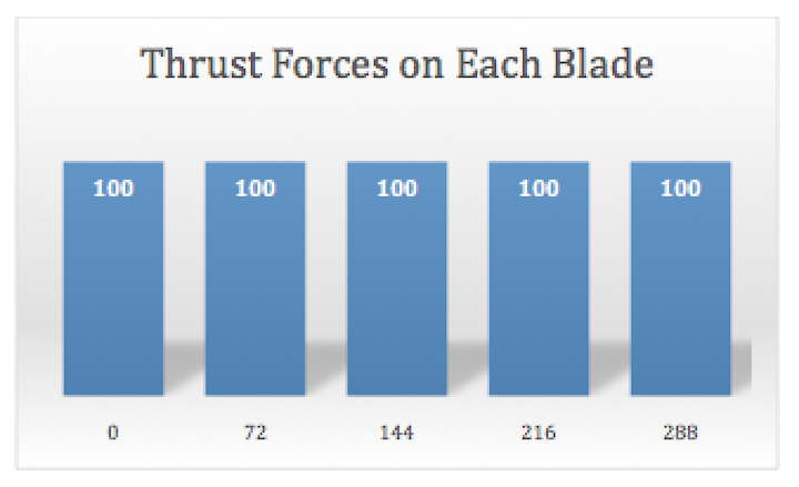 Fig. 1. Thrust produced by each blade in a new five-bladed,
mixed-flow, single-stage pump.
As long as the net thrust of all five blades is directed along a line parallel with the shaft, and that line is located within the shaft diameter, there is no significant hydrodynamic unbalance. Consequently, in new pumps or those in which there is no significant wear and blade symmetry is preserved, hydrodynamic unbalance is not a problem.
When a pump becomes worn, however, blades may exhibit thinning and erosion and, perhaps, have areas with concave dimples in the metal, especially near trailing edges and behind leading edges where cavitation typically occurs. If the impeller is sent to a shop, and the repairs are done to minimize cost and downtime, the work may change some of the impeller’s performance parameters in the following way.
If the thinned-out areas are simply removed and smoothed with a grinder, blade performance can be affected. First, shortening the width of the blade can reduce the amount of thrust it produces. Secondly, the centroid of thrust of the blade, where the individual blade’s thrust is centered, may shift to a new point. Third, trimming the ends of the blade to remove feathered material can allow more recirculation around the end of the blade through the now slightly larger gap between the blade and the bowl.
In short, repairs that affected the area and length of the blade, the thickness and cross-sectional profile of the blade, or the smoothness of the blade surface with respect to water flow can affect the amount of thrust an individual blade produces and where the centroid of its thrust occurs.
Figure 2 depicts the resulting thrust pattern of the five blades of the same hypothetical pump after it has become worn and been repaired several times. The pump’s overall capacity to move water has dropped about 3.2%. Recent repairs to the pump impeller, which were about the same as prior repairs, included the following.
1. Thinned and perforated areas in the blades were removed and ground smooth.
2. Areas exhibiting cavitation dimples were filled in by brazing and then smoothed out by hand-grinding.
3. Blade edges that had feathered into razor sharpness due to contact with the bowl had the razor edges knocked off and smoothed over.
4. Because the repair work listed in items 1 through 3 slightly rearranged the mass distribution of the impeller, the impeller and shaft were re-balanced on a balance stand.
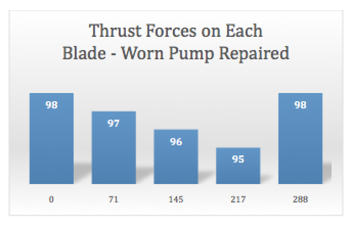 Fig. 2. Thrust produced by each blade in a five-bladed, mixed-flow,
single-stage pump that had become worn and was then repaired.
Note in Fig. 2 that besides changes in thrust, there also has been some rearrangement of the angles between the blades. The blades themselves have not been repositioned. The point on each blade where the thrust is centered has slightly shifted due to the changes made to the blade by wear and repairs.
Overall, as Fig. 2 infers, the thrust produced by the five blades is no longer symmetric about the pump axis, as was the case when the pump was new. As expected, the total thrust is a bit less than before due to the effects of wear and the accumulation of repair changes. What may not be expected, however, is that the overall thrust vector of the combined five blades is no longer centered within the pump shaft diameter. The net thrust is now offset from the pump shaft center line.
The changed net-thrust vector combined with the offset distance creates a moment, similar to that created in a two-plane unbalance as discussed before. This moment, which did not exist when the pump was new, is only noticeable when the unit is pumping liquid and the blades are creating thrust. If the moment is sufficiently large, it generates vibrations in the pump when it is operating.
This is an important point. Repairs to the impeller may unavoidably require removal of damaged material, as well as require the addition of material to fill in voids and concavities. These changes can affect the performance of the blades so that they are no longer symmetric with one another with respect to thrust. The mass distribution changes in making repairs will also affect the dynamic balance of the impeller and shaft.
Since the pump impeller and shaft are rebalanced when all the repair work has been completed, the fact that there will now be hydrodynamic unbalance when the pump is operating is a latent condition that does not show up on the balance machine.
INDICATIONS OF HYDRODYNAMIC UNBALANCE
So how does this type of hydrodynamic unbalance the performance of a large pump?
One thing that it does is increase the wear and fatiguing of thrust bearings, collars, and seals. Instead of an even application of thrust on the bearing or collar, a more pronounced cyclic thrust load is applied. Also, the shaft bearings at both ends may be subject to higher vibrational loading.
If the pump is vertical and has a lower bushing under the impeller, the bushing will likely see increased wear in a conical pattern. The moment created by unbalanced thrust will cause the pump shaft to precess or wobble like a top.
There are several things that may indicate hydrodynamic unbalance has been created by repair work.
1. Dimensional inspection of the blades finds significant differences among them, especially in width in the outer areas where some blades have had more material removed than others. An approximation of the variations in thrust can be made by comparing the total blade areas of each blade with one another.
2. Inspection of the counterbalancing weights added to effect balance of the repaired impeller and shaft may reveal that an unusually large amount of weight was used to counter significant blade material removal. These weights are often added inside the impeller hub and affixed to the hub by brazing.
3. The repair proposal will indicate removal of damaged material and filling in cavitation-damaged areas by brazing and grinding without ensuring that the dimension symmetry and profile of the blades is maintained or re-established.
AN ASIDE
As a related aside, a somewhat reverse problem was noted to occur in a large, single-stage mixed-flow pump when the repair shop indicated it had improved the performance of the pump. This was done by 1) re-profiling the blades to make them more hydrodynamically efficient; and 2) slightly increasing the width of the blades to improve pumping capacity. In this case, however, the pump motor was just equal to the task of starting and operating the pump. The extra capacity in the pump after completion of the repairs kept it from starting: The motor couldn’t synchronize to the power supply due to the now greater required start-up torque of the pump.
The refurbished pump was not, at first, suspected as being the cause of the problem. After all, the vendor indicated that the unit had been improved. (Improved is better, right?) The pump motor, whose performance had not changed (as verified by standard motor testing), was the leading suspect and, initially, expensive plans were made to change it out.
The problem was eventually solved after a bit of engineering investigation: removing the improved pump impeller and re-installing an old, unimproved impeller, whose performance matched the pump’s previously unimproved impeller. Once this was done, the pump started without a problem.TRR
ABOUT THE AUTHOR
Randall Noon is a registered professional engineer and author of several books and articles about failure analysis. He has conducted root-cause investigations for four decades, in both nuclear and non-nuclear power facilities. Contact him at noon@carsoncomm.com.
Tags: fluid handling, rotating equipment, maintenance, reliability, pumps, motors, seals, bushings, couplings, balancing, alignment, mounting bases, piping, vibration analysis

