Unless pump-piping configurations and associated layout have been determined by thoughtful design, things often go wrong. Therefore, distinctions must be made between the implementation tasks assigned to pipe fitters and the reliability-focused engineering tasks assigned to piping designers.
Accurate computer models and suitable software are used by reliability-focused plants. Accordingly, these plants obtain the lowest stress, most cost-effective and least-risk pipe installation by design, and not by any of the less dependable means.
Based on computer simulations, fixed and sliding pipe supports are located so as not to let thermal movements exert undue loads on pump nozzles. At some locations, the pipe must be suspended by tension springs; at other locations the pipe must rest on suitably restrained compression springs. The weight of insulation and, sometimes, even ice or snow loads must be considered by the designer.
PAY SPECIAL ATTENTION TO SLIDING SUPPORTS & INSTALLATION SEQUENCE
There is a widely overlooked item on sliding supports: Steel-Teflon-Steel is not usually a satisfactory sliding support. The steel plates (“shoes”) will oxidize and, due to surface roughness, dig into the Teflon. Best practice is to use Steel-Teflon-Teflon-Steel, in which case Teflon will slide on Teflon with considerable ease, thus providing long-term satisfactory sliding action.
Best practice requires installation of piping from vessels or other structures upstream of the pump and toward the pump suction nozzle, to a point about 10 to 15 ft. (2 to 3 m) from the nozzle. Then, one places a pipe flange at the suction nozzle and works toward the pipe run that had been terminated 10 to 15 ft. upstream. The same work sequence is next utilized on the downstream piping.
On the downstream pipe installation, one would install pipe from receivers, destination vessels, or other structures downstream of the pump and install pipe toward the pump’s discharge nozzle. This downstream pipe installation sequence should initially terminate at a point about 10 to 15 ft (2 to 3 m) from the pump discharge nozzle. Then, one places a pipe flange at the discharge nozzle and works toward the pipe run that had been terminated 10 to 15 ft. downstream.
Upstream and downstream of the process pump, the final connections are then made either at gasketed pipe flanges or by welding. While making these final connections at both upstream and downstream terminations 10 to 15 ft. from the pump, dial indicators set up to monitor pump-nozzle and bearing-housing movement must not show displacements of more than 0.002 inches (0.05 mm).
MONITOR PIPE STRESS WHILE BOLTING UP
Pumps are designed to allow only limited loading of pump suction and discharge nozzles. Misaligned pipes can produce forces and moments on pump nozzles that vastly exceed maximum allowable values. Excessive piping loads can cause high vibration, shaft misalignment, seal distress, bearing overload, and coupling failures.
To keep within allowable limits, several dial indicators are set up to monitor the pump’s sensitivity to pipe stress. Dial-indicator movement is monitored while initial and final bolt tightening is in progress. Four dial-indicator stems are set to contact pump and driver feet and detect unsupported (soft-foot) conditions; two additional dial indicators observe the pump bearing housing for movement in the x and y-directions. Any indicator-needle displacement of more than 0.002 inches (0.05 mm) will require corrections to the piping.
Again, a process pump should never be allowed to serve as a pipe support. Chain-falls or come-along hoists and other supplementary mechanical tools (pulling devices) are never allowed or used by reliability-focused pump-installation crews.
In general, maximum misalignment pipe-flange to pump-nozzle and flange to flange should be kept within the limits of Fig. 1. Before allowing connections to be made, the two mating faces should be:
1. Parallel with each other within 1/32 in. (0.8 mm) at the extremity of the raised face, i.e., “A” and “B” should
differ by no more than 1/32 in. (0.8 mm)
2. Concentric so their centerlines coincide within 1/8 in., i.e., the offset “C” should not exceed 1/8 in. (3 mm);
“D” should allow insertion of either a gasket or blind.
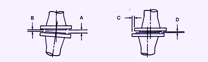 Fig. 1. Limits of flange deviations.
When it comes to matters of pump-piping misalignment, there are two important, yet simple and very useful tests:
1. It must be possible for an average-size worker to push the misaligned piping into place with his/her two hands,
without using any supplementary mechanical tools
2. Once the gasket has been inserted and the bolts torqued up, dial indicators observing the upwards and sideways
motion at the pump suction and discharge nozzles cannot exceed 0.002 inches (0.05 mm) in any direction.TRR
Editor’s Note: Click Here To Download A Newly Updated List Of Heinz Bloch’s 24 Books
ABOUT THE AUTHOR
Heinz Bloch’s long professional career included assignments as Exxon Chemical’s Regional Machinery Specialist for the United States. A recognized subject-matter-expert on plant equipment and failure avoidance, he is the author of numerous books and articles, and continues to present at technical conferences around the world. Bloch holds B.S. and M.S. degrees in Mechanical Engineering and is an ASME Life Fellow. These days, he’s based near Houston, TX.
Tags: reliability, availability, maintenance, RAM, pumps, piping configurations, piping layout, pipe stress, misalignment

