In some cases, a significantly greater set of data is required to make improvements to a troubled system. When using individual technologies, most technicians are looking for single problems that relate specifically to the selected technology. Consequently, they will often miss minor issues that this technology does not detect. If the problem worsens, or if additional defects are triggered by a fault, the proper application of data becomes paramount.
In this short case study, we review an ID fan for a boiler that has a number of significant issues. To identify primary drivers of the defects and the impact the defects had on surrounding equipment and structure required multiple technologies.

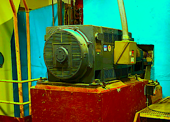
Fig. 1. ID Fan on fifth floor of the facility.
The fan is driven by either a 1200 rpm motor or a steam turbine. At some point, however, the turbine seized and the fan shaft and coupling at the turbine end was cut off short. There was a high 1X vibration associated with the electric motor and fan that could be felt through the building. A vibration impulse test was performed and the natural frequency at the corner of the building where the fan was located was 1210 cpm, which was 10-20 rpm off the operating speed of the fan and other electric-motor-driven equipment in this area.

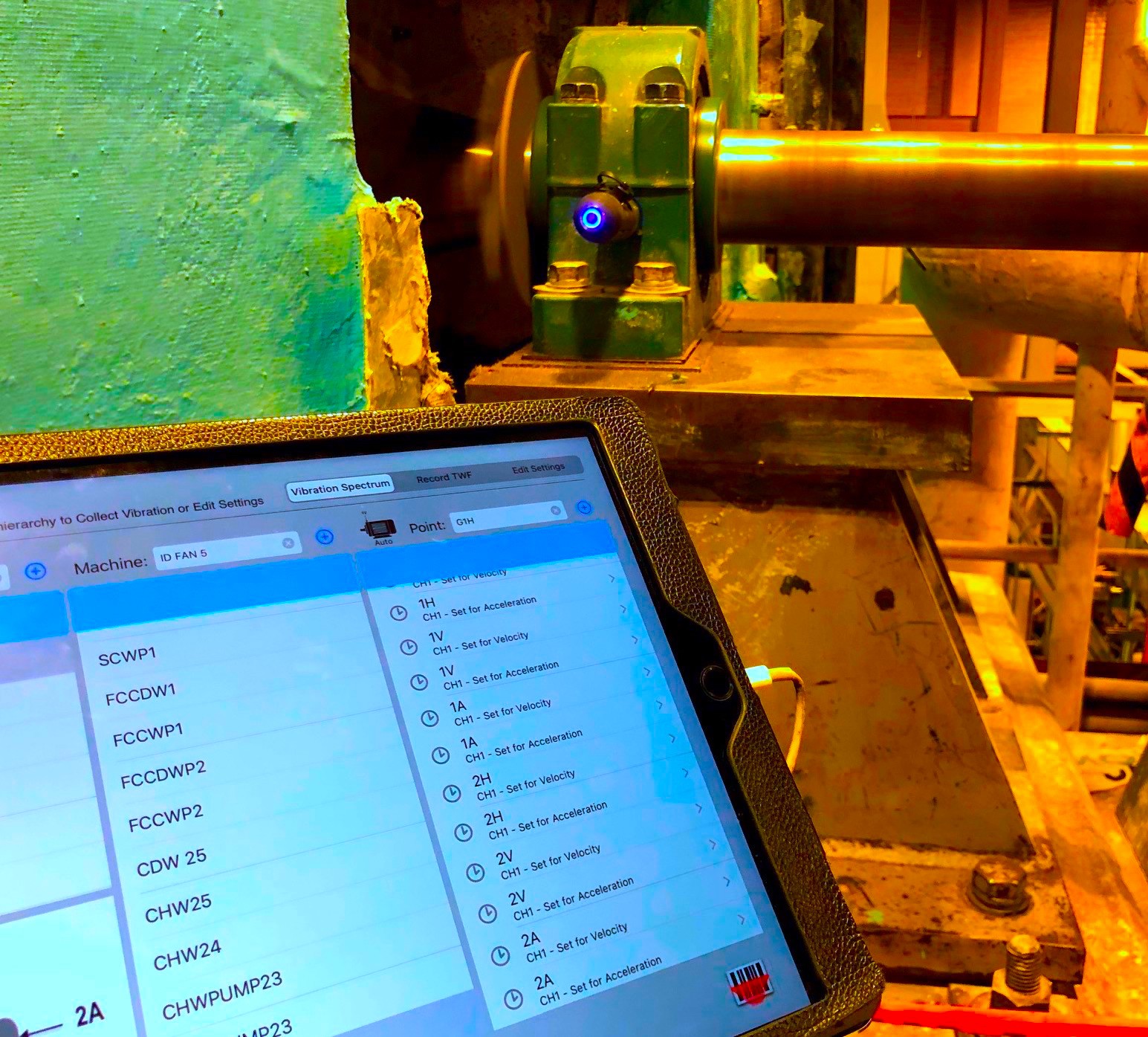
Fig. 2. Taking GTI Vibration data from the steam turbine end of the fan after the shaft was repaired.
During the initial work, as shown in the video at the end of this article, defects were found in the bearing pedestals, motor base, operation of the fan, the fan itself, and the structure at that location of the building. Additionally, work had been performed to “stiffen” the structure surrounding the motor and fan. This appeared to have the adverse effect of tuning the structural vibration closer to the operating speed of the motor and fan and tied main beams together with a welded structure transferring more vibration energy lower into the building.
Before work was finally performed on the equipment, the fan bearings had catastrophically failed right before motion amplification was to be performed with an RDI Technology motion amplification system. The primary driver behind the vibration happened to be the fan itself, as the speed and pressure were too great for the application, causing substantial backpressure.
Data was collected using an EMPATH Electrical Signature Analyzer, GTI vibration equipment, and RDI Technologies motion amplification equipment. the Electrical Signature Analysis (ESA) detected fan, looseness and unbalance, which was also detected when vibration and mechanical-impulse testing was performed to view phase differences. Motion amplification tied everything together by providing a visual representation of the different defects.

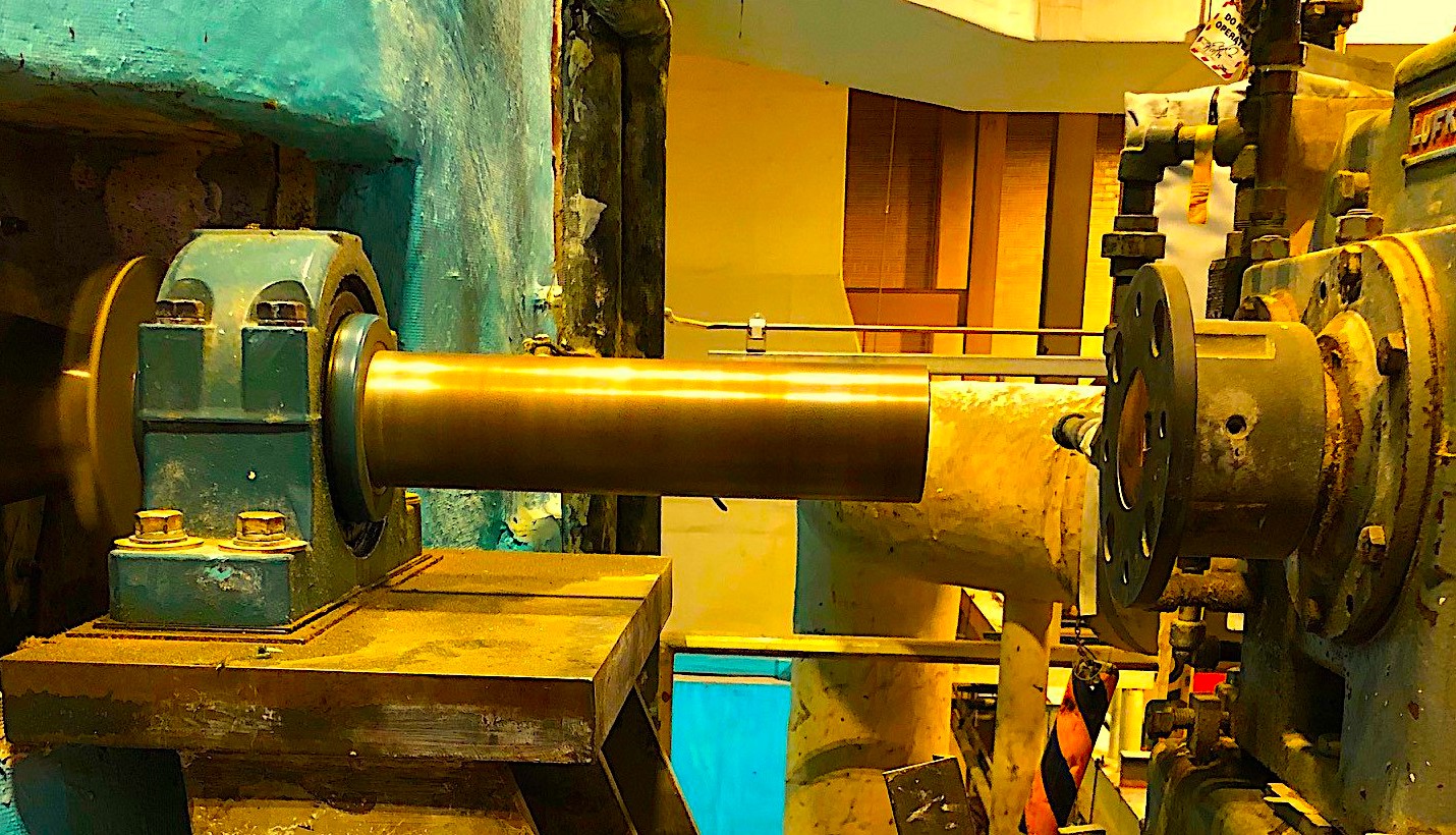
Fig. 3. As noted, the bearing is on the inside of the pedestal instead of centered.

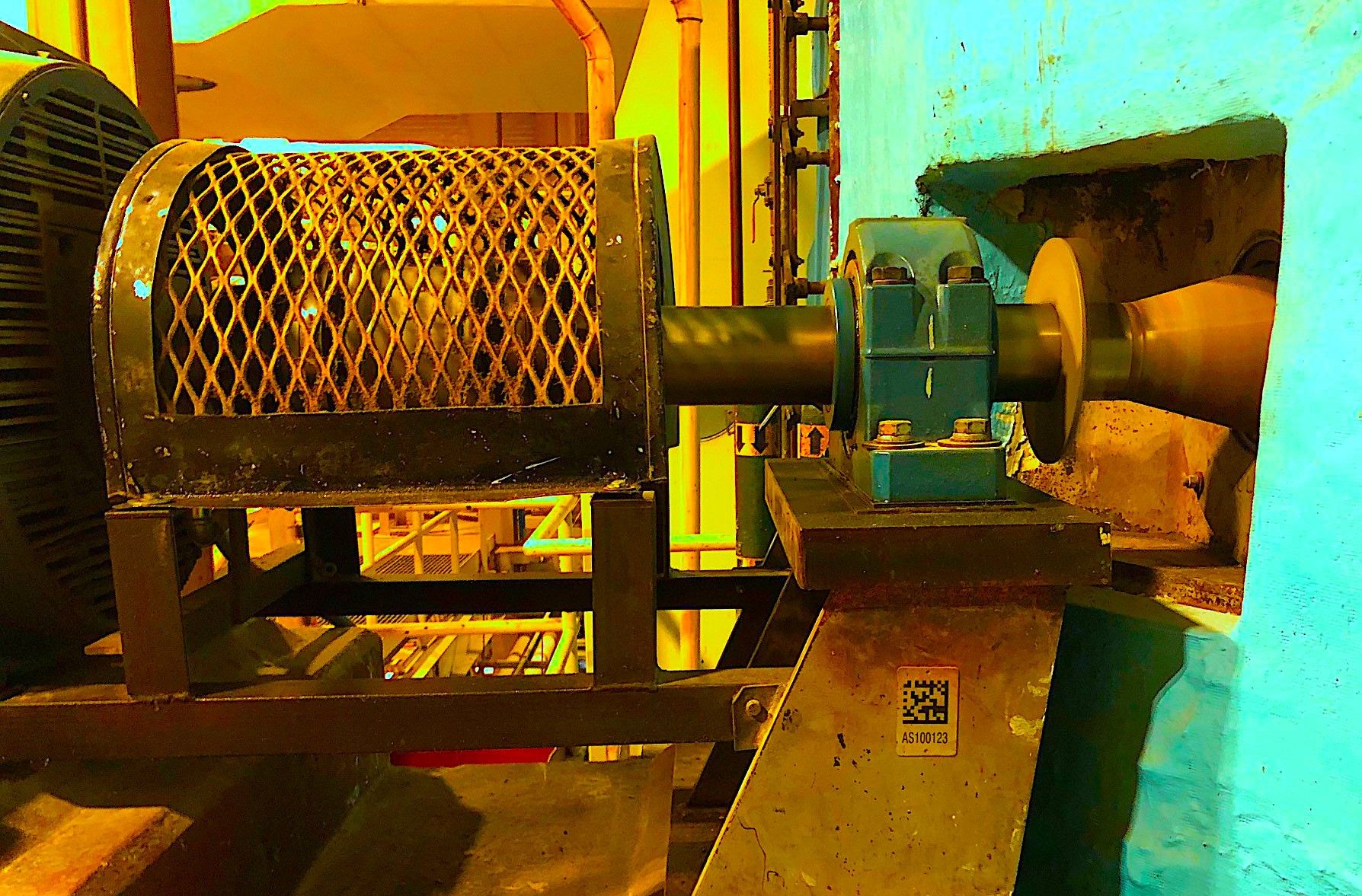
Fig. 4. The motor-end fan bearing is in a good position on the pedestal.
Some corrections were made, including repairs to the fan, and a new balloon shaft was fabricated and installed. The followup vibration and motion-amplification data showed significant improvement. Before- and after-data analysis was performed showing improvements from the partial repairs.TRR
Click Here To View The Referenced Video Regarding Data And Motion-Amplification Results On YouTube
Or Go To:
https://youtu.be/8b9DYkk-_nA
ABOUT THE AUTHOR
Howard Penrose, Ph.D., CMRP, is Founder and President of Motor Doc LLC, Lombard, IL and, among other things, a Past Chair of the Society for Reliability and Maintenance Professionals, Atlanta (smrp.org). Email him at howard@motordoc.com, or info@motordoc.com, and/or visit motordoc.com.
Tags: motors, motor testing, ID fans, balloon shafts, boilers, steam turbines, bearings, couplings, motion-amplification, Electrical Signature Analysis, ESA, vibration-impulse testing, vibration analysis, reliability, availability, maintenance, RAM


